Using POINT to print to a certain location
In Fig. 9 above, we see the main difference between PRINT items on Layer 0 and the other layers and that's none other than the previously mentioned ability to place them in any X and Y coordinate we please. This diagram assumes a standard 8x8 character size but where you only saw rows in Fig. 8, here you also see a pixel value. This corresponds to the placement of each row and column in Layer 0 but in fact, it could be anything within the boundaries of the horizontal and vertical resolution. Let's switch layers and try to do the same thing:
LAYER 1,1:PRINT POINT 248,176;"*"
Unlike before you'll will not get an 5 Out of screen, 0:1 error and you will get an asterisk at the rightmost edge of the screen like we expected to get the first time we gave the PRINT AT 22,31 command. The two values correspond to 22 times the character height and 31 times the character width (both of which are 8 pixels). You can see at the same time the notion of the free placement of characters as the addressing of the location is now in pixels and not the fixed rows and columns. What's also immediately visible is that addressing the location on screen in pixel coordinates is different as it reverses the order of the location parameters from y,x to x,y and that's done to match the syntax of the rest of the graphics commands that accept pixel coordinates as parameters . To replicate the behaviour of the first PRINT AT command on Layer 0 and get an error, we will need to place the output of print, outside the boundaries of the screen like so:
LAYER 1,1: PRINT POINT 256,0;"*"
would produce the same exact error. To properly calculate where to print if you want to keep your coordinates cell-based instead of pixel-based, a simple function could do that for you quite easily. In Fig. 8 as well as Fig. 9 we've done that for you assuming a standard font, but what about a shorter, or perhaps taller font? It's quite simple if you keep in mind that, if you follow the heights defined earlier, you can find exactly how many rows and columns you can fit in your screen. Note that POINT's arguments must not begin with a parenthesis because it will be evaluated as a function and attempting to store the line you're typing will fail.
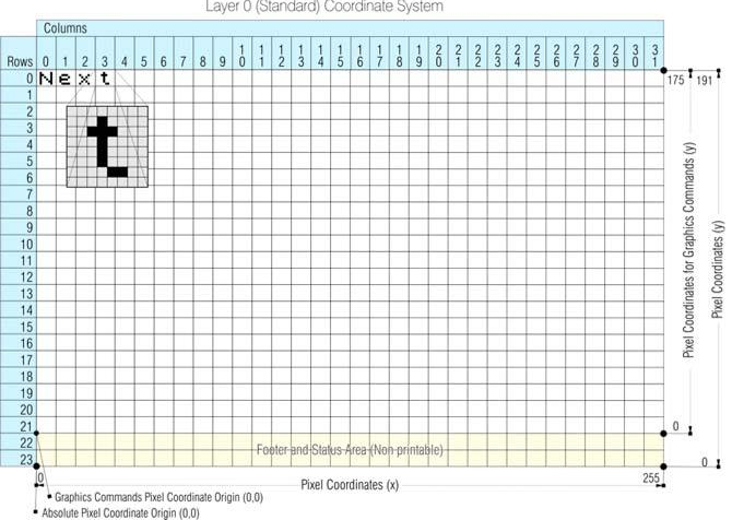
Fig. 10 – High Resolution coordinate system for PRINT and INPUT
The following –very slow– program demonstrates exactly how things are positioned on screen with every change in Layer and furthermore gives you some insight on how PRINT POINT as well as –indirectly– PRINT AT is affected every time your screen mode changes. Try to walk through the program to figure out how it operates:
ZX Spectrum Next User Manual, 3rd Edition (ISBN 978-1-5272-5496-1), written and illustrated by Phoebus R. Dokos. Copyright © 2020-2024 Phoebus Dokos / SpecNext Ltd. Licensed under CC BY-NC-SA 4.0. This is a transcription and can contain errors; check any doubt against the printed page.