Pages 81–94 · Markdown
Chapter 14 – More about PRINT and INPUT
Coordinate Systems
Before we go into more detail about how we can exercise a bit more control on PRINT and INPUT it is useful to understand a little bit about the way NextBASIC views character positioning on the screen. Due to the requirements for backwards compatibility with previous Sinclair computers, NextBASIC uses two distinct coordinate systems to keep track of where text is input or outputted. The first –or legacy– system is based on a virtual matrix that exists on screen and organises it in rigid rows and columns. The second, is more precise and allows for freely positioned columns and rows along the x and y-axes. Additionally the legacy coordinate system has been extended to allow for direct manipulation of the footer bar and status area for layers other than Layer 0, which is not normally possible in the legacy system.
Screen Modes and Pixel Coordinates
In order to make a concrete distinction between the two coordinate systems, we should first discuss a little bit about the ZX Spectrum Next's display system. We will revisit this again in Chapters 15 and 16 in more detail as these chapters deal with the full graphics capabilities of the computer rather than the subset dedicated to screen character manipulation, but for now let's enumerate the screen modes in a simple fashion.
The ZX Spectrum Next has 12 distinct graphics modes broken into 4 groups –or layers– with an additional Sprite Layer which we will not be covering in this chapter . These modes are accessed using the LAYER command with the exception of Layer 3 (Character Graphics) and the higher resolution Layer 2 modes and they are the following:
- Layer 0
- Layer 0 – Standard Spectrum (ULA) mode, 256 w x 192 h pixels, 8 colours total (2 intensities), 32 x 24 cells, each capable of displaying 2 colours
- Layer 1
- Layer 1, 0 – LoRes (EnhancedULA) mode, 128 w x 96 h pixels, 256 colours total, 1 colour per pixel
- Layer 1, 1 – Standard Res (EnhancedULA) mode, 256 w x 192 h pixels, 256 colours total, 32 x 24 cells, each capable of displaying 2 colours
- Layer 1, 2 – Timex HiRes (EnhancedULA) mode, 512 w x 192 h pixels, 256 colours total, only 2 colours on screen
- Layer 1, 3 – Timex HiColour (EnhancedULA) mode, 256 w x 192 h pixels, 256 colours total, 32 x 192 cells, each capable of displaying 2 colours
- Layer 2
- Layer 2 – 256 w x 192 h pixels, 256 colours total, one colour per pixel
- Layer 2,2 – 320 w x 256 h pixels, 256 colours total, one colour per pixel
- Layer 2,3 – 640 w x 256 h pixels, 16 colours total, one colour per pixel
- Layer 3
- Layer 3,0 – Text mode, 320 w x 256 h pixels, 256 colours total, 40 x 32 cells each capable of displaying 2 colours
- Layer 3,1 – Text mode, 640 w x 256 h pixels, 256 colours total, 80 x 32 cells, each capable of displaying 2 colours
- Layer 3,2 – Graphics mode, 320 w x 256 h pixels, 256 colours total, 40 x 32 cells each capable of displaying 16 colours
- Layer 3,3 – Graphics mode, 640 w x 256 h pixels, 256 colours total, 80 x 32 cells, each capable of displaying 16 colours
Layers 2,2 as well as 2,3 together with Layer 3 are not currently available to PRINT and INPUT and therefore won't be discussed in this chapter; they are mentioned here for completeness.
Technically speaking, Layer 1,1 is the same as Layer 0 with extra colour capabilities however NextBASIC treats them differently to maintain a consistent way of addressing the extra capabilities of the ZX Spectrum Next's EnhancedULA. The legacy coordinate system we discussed above applies only on Layer 0, whereas Layers 1 and 2 use the new system.
There are three major differences between Layer 0 and Layers 1 and 2 as far as character positioning goes. There are more differences but we will examine these in turn in the special graphics Chapters 15 – 17. These are:
- Layer 0 is organised in a strict 32 columns by 24 rows matrix while the rest can both position characters on a similar matrix (according to character size), or, if so desired, anywhere along the y and x axes.
- The user cannot –normally– position characters on the two bottom rows of the Layer 0 screen while this is possible in the other layers.
- Layer 0 pixel coordinates begin at the bottom left corner and extend up and to the right while for the rest of the layers, pixel coordinates begin at the top left corner and extend down and to the right. This particular difference is not important for character placement on Layer 0 but it is for the rest of the layers and definitely, as we are going to see further down this manual, extremely important for positioning graphics.
Changing the size of characters
With the exception of Layer 0, which has, as we mentioned, a rigid organisation of character positions on screen in a 32 x 24 character matrix, all other layers have the ability to position characters either rigidly as above (ie. in a rows x columns matrix) or freely according to pixel position of each character matrix's top left corner.
Character size can be modified horizontally with the following sequence:
PRINT CHR$ 30; CHR$ n;
where n can be a number from 3 to 8, which sets the width of all characters displayed on screen from a minimum of 3 to a maximum of 8 pixels wide. Character size is modified vertically by issuing:
PRINT CHR$ 29; CHR$ n;
where n can be a number from 0 to 3, which sets the height of all characters displayed on screen to the following predetermined heights in pixels:
| Value of n | Size (pixels) | Description |
|---|---|---|
| 0 | 8 | Normal Size |
| 1 | 16 | Double Size |
| 2 | 6 | Reduced Size |
| 3 | 12 | Double Reduced Size |
These sequences which are more appropriately called control codes, are character size shortcuts for text windows. These can also be used on Layer 0 but you would need to open a window first when in that mode. The rest of the layers have predefined and pre-opened full-screen text windows and therefore these control codes work there by default. We will discuss text windows at length in Chapter 20 – Channels, Streams and Windows so for now keep these two control codes in mind as only working outside Layer 0. They are extremely important to know, as they modify the behaviour of the AT and TAB modifiers we will examine below.
Using AT to print to a certain location
You have already seen PRINT used quite a lot, so you will have a rough idea of how it is used. Expressions whose values are printed are called PRINT items, and they are separated by commas, semicolons and apostrophes, which are called PRINT separators. A PRINT item can also be nothing at all, which is a way of explaining what happens when you
use two commas in a row.
There are two more kinds of PRINT items, which are used to tell the computer not what, but where to print. For example PRINT AT 11,16;"*" prints a star in the middle of the screen in Layer 0.
The modifier
AT vertical_position, horizontal_position
moves the PRINT position (the place where the next item is to be printed) to the vertical and horizontal position specified. Horizontal positions are measured in columns and vertical positions in rows however for layers other than Layer 0, the number of columns and rows varies according to the size of characters used (and for HiRes mode the horizontal resolution as well). Character sizes are set according to the previous section, however for AT usage purposes, we need to note that double-width and double-height character sizes do not modify the maximum columns and rows AT will accept as parameters, so if for example you use PRINT CHR$ 29; CHR$ 1 for characters that are 16 pixels high, you will still get a maximum of 24 rows for AT purposes.
You may have noticed at the beginning of this chapter that we discussed Layer 0 as being organised for character printing purposes, in a matrix of 24 rows by 32 columns. As you will see however when in Layer 0, NextBASIC will not give you access to the last two rows since, as we discussed in Chapter 1, the bottom two rows of the screen are reserved. This is also true for bitmap graphics commands as you will see in Chapters 17 and 18. We will expand further on the possible combinations for AT but for now give the command:
PRINT AT 22,31;"*"
and you will immediately receive error 5 Out of screen, 0:1. It's not difficult to understand why that happened. As we can see in Fig. 8 below, for the purposes of printing via NextBASIC1, your computer has a vertical resolution of 192 pixels. Since, as we learned in Chapter 13, each character is 8 pixels high, we can make a quick division and see that 192 ÷ 8 = 24. Knowing that the two last lines are reserved and not accessible to us, we can reduce our available rows by a further 16 pixels (or 2 rows) so we get a total 22 rows. As your computer starts counting from zero, 22 rows would go up to 21 as a value, which in turn explains why you received the error.
Rows on which we can place output using AT, are numbered therefore from 0 (at the top) to 21, and columns from 0 (on the left) to 31.
This situation changes when we change layers and go to the other two groups (remember that Layer 3 and the higher resolution Layer 2 sublayers are excluded). As discussed previously, columns and rows on these are calculated according to the width of characters that we have selected with the control codes. Before we illustrate graphically how the screen is organised, the following table will give you the possible combinations in columns per character width. Remember that you can also figure this out on your own by dividing the maximum resolution of the layer you're using by the selected character width.
| Number of columns per Layer | |||
|---|---|---|---|
| Character width (in px) | LoRes Layer 1,0 (128 x 96) | HiRes Layer 1,2 (512 x 192) | Standard Res Layers: 1,1–1,3 – 2 (256 x 192) |
| 3 | 42 | 170 | 85 |
| 4 | 32 | 128 | 64 |
| 5 | 25 | 102 | 51 |
| 6 | 21 | 85 | 42 |
| 7 | 18 | 73 | 36 |
| 8 | 16 | 64 | 32 |
Table 6 – Column positions for PRINT according to character size
1 The maximum screen resolution of the ZX Spectrum Next is 320 x 256 pixels (or 640 x 256 half-width pixels), however these resolutions are only available to Layers 2,3 and Sprite Layers as we will see in the following chapters.
Table 6 above, showed us that although we could pack our screen with 170 characters per line, in practice 3 pixel wide fonts are almost unreadable, even at the highest available resolution of Layer 1,2. In the example program that's meant to demonstrate character cells for the AT modifier (but written using the POINT modifier strangely enough!) we're including below, you can see all the possible combinations for all layers.
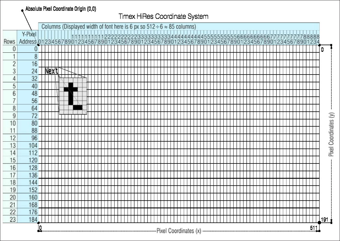
Fig. 8 – Layer 0 coordinate system for PRINT and INPUT
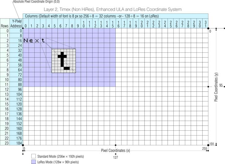
Fig. 9 – LoRes and Standard Resolution coordinate system for PRINT and INPUT
The author's personal preference is the 128 column text of HiRes Layer 1,2 as it's clear enough to read but not too big as to not be able to fit a lot of information onto your screen.
Using POINT to print to a certain location
In Fig. 9 above, we see the main difference between PRINT items on Layer 0 and the other layers and that's none other than the previously mentioned ability to place them in any X and Y coordinate we please. This diagram assumes a standard 8x8 character size but where you only saw rows in Fig. 8, here you also see a pixel value. This corresponds to the placement of each row and column in Layer 0 but in fact, it could be anything within the boundaries of the horizontal and vertical resolution. Let's switch layers and try to do the same thing:
LAYER 1,1:PRINT POINT 248,176;"*"
Unlike before you'll will not get an 5 Out of screen, 0:1 error and you will get an asterisk at the rightmost edge of the screen like we expected to get the first time we gave the PRINT AT 22,31 command. The two values correspond to 22 times the character height and 31 times the character width (both of which are 8 pixels). You can see at the same time the notion of the free placement of characters as the addressing of the location is now in pixels and not the fixed rows and columns. What's also immediately visible is that addressing the location on screen in pixel coordinates is different as it reverses the order of the location parameters from y,x to x,y and that's done to match the syntax of the rest of the graphics commands that accept pixel coordinates as parameters . To replicate the behaviour of the first PRINT AT command on Layer 0 and get an error, we will need to place the output of print, outside the boundaries of the screen like so:
LAYER 1,1: PRINT POINT 256,0;"*"
would produce the same exact error. To properly calculate where to print if you want to keep your coordinates cell-based instead of pixel-based, a simple function could do that for you quite easily. In Fig. 8 as well as Fig. 9 we've done that for you assuming a standard font, but what about a shorter, or perhaps taller font? It's quite simple if you keep in mind that, if you follow the heights defined earlier, you can find exactly how many rows and columns you can fit in your screen. Note that POINT's arguments must not begin with a parenthesis because it will be evaluated as a function and attempting to store the line you're typing will fail.
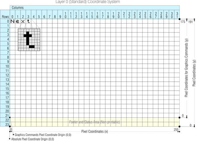
Fig. 10 – High Resolution coordinate system for PRINT and INPUT
The following –very slow– program demonstrates exactly how things are positioned on screen with every change in Layer and furthermore gives you some insight on how PRINT POINT as well as –indirectly– PRINT AT is affected every time your screen mode changes. Try to walk through the program to figure out how it operates:
  10 REM First we disable LAYER
     2 and then we set Standard
     ULA Display Mode
  20 LAYER 2,0
  30 LAYER 0
  40 MaxX,MaxY=128,96
  70 mul,div,add=1,1,0
 100 chsz,h=8
 120 FOR m=0 TO 5
 130 n,d=0,1
 150 IF m=0 THEN GO TO 370: REM
     Layer 0  not supported by
     PRINT POINT
 160 FOR a=3 TO 8
 180 FOR b=0 TO 3
 190 n,d=0,1
 210 PROC LayChange(m,a,b)
 220 FOR r=0 TO (MaxY*mul)-1
     STEP h
 230 FOR c=0 TO (MaxX*mul)-chsz
     STEP chsz
 235 row = (r+add)/div
 240 IF r=0 AND c<>0 THEN PRINT
     POINT
     c,row;d : d+=1
 250 IF c=0 AND r=0 THEN PRINT
     POINT
     c,row;n : n+=1
 260 IF c=0 AND r<>0 THEN PRINT
     POINT
     c,row;n :n+=1
 270 IF c<>0 AND r<>0 THEN
     PRINT POINT
     c,row;"*"
 280 IF n=10 THEN n=0
 290 IF d=10 THEN d=0
 300 NEXT c
 310 IF c=1 THEN n=0
 320 NEXT r
 330 PAUSE 0
 340 IF m=0 THEN GO TO 370
 350 NEXT b
 360 NEXT a
 370 NEXT m
 380 LAYER 0
 390 LAYER 2,0
 400 STOP
1000 DEFPROC LayChange(mode,ch,he)
1010 div,add, maxX, maxY, mul,
     chsz=1,0,128,96,2,ch
1070 IF he=0 THEN h=8
1080 IF he=1 THEN h=16
1090 IF he=2 THEN h=6
1100 IF he=3 THEN h=12
1110 REM Layer 0 is not covered
     as PRINT POINT doesn't work
1120 IF mode=1 THEN LAYER 1,0:
     CLS:mul=1:PRINT CHR$ 30;
     CHR$ ch:PRINT CHR$ 29; CHR$
     he:PRINT AT 0,0;"LoRes"''"
     CSIZE (HxW)  ";h;" x
     ";chsz'"PRESS ANY KEY":
     PAUSE 0:CLS:ENDPROC
1130 IF mode=2 THEN LAYER 1,1:
     CLS : PRINT CHR$ 30; CHR$
     ch:PRINT CHR$ 29;CHR$ he:
     PRINT AT
     0,0;"EnhancedULA"'"CSIZE
     (HxW)  ";h;
     " x ";chsz'"PRESS ANY KEY"
     :PAUSE 0:CLS:ENDPROC
1140 IF mode=3 THEN LAYER 1,2:
     CLS:MaxX=256:PRINT CHR$ 30;
     CHR$ ch:PRINT CHR$ 29; CHR$
     he:PRINT AT 0,0;"Timex
     HiRes"'"CSIZE (HxW)  ";h;"
     x ";chsz'"PRESS ANY KEY":
     PAUSE 0:CLS:ENDPROC
1150 IF mode=4 THEN LAYER 1,3:
     CLS:PRINT CHR$ 30; CHR$ ch:
     PRINT CHR$ 29; CHR$ he:
     PRINT AT 0,0;"Timex
     HiColour"'"CSIZE (HxW)
     ";h;" x ";chsz'"PRESS ANY
     KEY":PAUSE 0:CLS:ENDPROC
1160 IF mode=5 THEN LAYER 2,1:
     CLS:PRINT CHR$ 30;CHR$
     ch:PRINT CHR$ 29; CHR$
     he:PRINT AT
     0,0;"Layer2"'"CSIZE (HxW)
     ";h;" x ";chsz'"PRESS ANY
     KEY":PAUSE 0:CLS:ENDPROC
SCREEN$
SCREEN$ is the reverse function to PRINT AT, and will tell you (within limits) what character is at a particular position on the screen. It uses line and column numbers in the same way as the Layer 0 version of PRINT AT, but enclosed in parentheses. For instance:
PRINT SCREEN$ (11,16)
will retrieve the star you printed in the first example of the previous section. SCREEN$ only works on Layer 0 and will return everything printed there, even if you switch layers during the process as long as the memory used (which is shared between Layers 0, 1 and 3 as you will see in Chapter 23) has not been overwritten by another display related command. Type:
10 LAYER 0:PRINT AT 11,11;"*"
20 LAYER 1,0:PRINT AT
   0,0;SCREEN$ (11,11)
You will get a huge * on the upper left corner of your screen even if the original * is not visible anymore on screen. Changing line 10 to LAYER 1,0 from LAYER 0 will produce a null string.
Characters taken from tokens print normally, as single characters, and spaces return as spaces. Lines drawn by PLOT, DRAW or CIRCLE, user-defined characters and graphics characters return as a null (empty) string, however. The same applies if OVER (See Chapter 16) has been used to create a composite character. The way that SCREEN$ works is that it matches the character in a screen location to the bitmapped image of the character in the ROM of NextZXOS. If they match it will return it. If the picture in the location doesn't match any known character it will return an empty string.
TAB
If you're familiar with word processing, other computers, or even typewriters, you may be also familiar with the concept of a tab, or tabulating character. What this does in other computers is to insert a special character which will move the cursor right by a predetermined amount of locations in order to arrive to a specific column in your text. The ZX Spectrum Next, doesn't quite work like this although the ending result on your screen is pretty much equivalent. The modifier:
TAB column
prints enough spaces to move the PRINT position to the column specified. It stays on the same line, or, if this would involve backspacing, moves on to the next one. Note that the computer reduces the column number modulo X with X being the maximum amount of columns available per the width of character chosen for each Layer (meaning it divides by X and takes the remainder); so for example for Layer 0, TAB 33 means the same as TAB 1.
The code:
PRINT TAB 30;1;TAB 12;"Contents"; AT
3,1;"CHAPTER";TAB 24;"page"
demonstrates, how you might print out the heading of a contents page on page 1 of a book (if that book was displayed using ZX Spectrum Next characters of course!)
Try running this:
10 FOR n=0 TO 20
20 PRINT TAB 8*n;n;
30 NEXT n
This shows what is meant by the TAB numbers being reduced modulo X. For a more elegant example, change the 8 in line 20 to a 6 or even try to implement this on a different layer such as the HiRes one as it allows more room for demonstration of this functionality by adding LAYER 1,2 before line 10.
As you'll see in Chapter 20, TAB accepts a two-byte parameter which means it accepts a maximum column number of 65535! Not that you'd ever want to use that!
Some small points:
- These new items are best terminated with semicolons, as we have done above. You can use commas (or nothing, at the end of the statement), but this means that after having carefully set up the PRINT position, you immediately move it on again which wouldn't usually be terribly useful.
- As a reminder, you cannot print on the bottom two rows (22 and 23) on the Layer 0 screen because they are reserved for commands, INPUT data (see below), reports/errors and so on. References to the bottom line usually mean line 21 and only apply to Layer 0.
- You can use AT to put the PRINT position even where there is already something printed; the old stuff will be obliterated when you print more.
CLS
Another statement that's connected with PRINT (although it's not only limited to it), is CLS. This clears the whole screen, something that is also done by CLEAR and RUN. The LAYER command does not clear the screen however, although it may switch to a new screen that has nothing on it. Do not assume a Layer is free of stuff just because you haven't used a command that outputs something on screen. Always give CLS after switching layers if you want to ensure a screen free of anything on it.
Scrolling
When the printing reaches the bottom of the screen, the latter moves its contents upwards, to clear room on the bottom for new content. You can see this if you go into the status area by using the Edit menu option Screen and then type:
CLS:FOR n=1 TO 22:PRINT n:NEXT n
and then do:
PRINT 99
a few times.
Depending on the layer you are on, the computer may pause its screen output for you to review the content being printed and ask you a question or may simply display a block cursor at the lower right corner and wait.
On Layer 0, if the computer is printing out reams and reams of stuff on screen, it asks you before continuing. You can see this happening if you type:
CLS:FOR n=1 TO 100:PRINT n:NEXT n
When it has printed a screenful, it will stop, writing scroll? at the bottom of the screen. You can now inspect the first 22 numbers at your leisure. When you have finished with them, press y (for yes) and the computer will give you another screen full of numbers. Actually, any key will make the computer carry on except n (for no), SYMBOL SHIFT and A (for STOP as you can see printed on your ZX Spectrum Next's keyboard2), SPACE, BREAK (or CAPS SHIFT and SPACE) or Esc (the latter if you have a PS/2 type keyboard) . These will make the computer stop running the program with a report D BREAK - CONT repeats. On other layers, the scroll? message is replaced by a block cursor (called the scroll prompt cursor) at the lower right corner. The only keys which will stop the scrolling in layers other than 0 are the Esc key if on a PS/2 keyboard or the BREAK key (CAPS SHIFT and SPACE). Everything else will scroll the screen.
Expanding on INPUT
The INPUT statement can do much more than we have told you so far. You have already seen INPUT statements like:
INPUT "How old are you?", age
in which the computer prints the caption How old are you? at the bottom of the screen, and then you have to type in your age.
In fact, an INPUT statement is made up of items and separators in exactly the same way as a PRINT statement is, so How old are you? and age are both INPUT items. INPUT items are generally the same as PRINT items, but there are some very important differences:
First, an obvious extra INPUT item is the variable whose value you are to type in – age in our example above. The rule is that if an INPUT item begins with a letter, it must be a variable whose value is to be input.
Second, this would seem to mean that you can't print out the values of variables as part of a caption; however, you can get round this by putting parentheses around the variable. Any expression that starts with a letter must be enclosed in parentheses if it is to be printed as part of a caption.
Any kind of PRINT item that is not affected by these rules is also an INPUT item. Here is an example to illustrate what's going on:
myage=INT(RND(100)):INPUT("I am ";myage;
". ");"How old are you?", yourage
myage is contained in parentheses, so its value gets printed out. yourage is not contained in parentheses, so you have to type its value in.
If you are in Layer 0, everything that an INPUT statement writes goes to the bottom part of the screen, which acts somewhat independently of the top half. In particular, its rows are numbered relative to the top line of the bottom half, even if this has scrolled the actual screen up (which it does if you type lots and lots of INPUT data).
To see how AT works in INPUT statements, try running this on Layer 0:
10 INPUT "This is line
   1.",a$; AT 0,0;"This is
   line 0.",a$; AT 2,0;
   "This is line 2.",a$; AT
   1,0; "This is still line
   1.",a$
2 This functionality comes from the original ZX Spectrum single key (or tokenised) entry and it's retained for compatibility reasons.
(Just press ENTER each time it stops.) When This is line 2. is printed, the lower part of the screen moves up to make room for it; but the numbering moves up as well, so that the rows of text keep their same numbers.
Now try this (again on Layer 0):
10 FOR n=0 TO 19: PRINT AT
   n,0;n;: NEXT n
20 INPUT AT 0,0;a$; AT 1,0;a$;
   AT 2,0;a$; AT 3,0;a$; AT
   4,0;a$; AT 5,0;a$;
As the lower part of the screen scrolls up and up, the upper part is undisturbed until the lower part threatens to write on the same line as the PRINT position. Then the upper part starts scrolling up to avoid this.
The other layers work in the same manner as described for PRINT items, that is in both rigid (cell matrix) and flexible (pixel coordinate) terms. To illustrate the difference, issue a LAYER 1,1 direct command and then modify the first example by first copying line 10 to line 20 and then changing all AT statements to POINT statements switching the x and y positions around, thus making the latter two parameters 0,16 and 0,8 respectively to reflect the height of characters (remember that on layers other than 0 character matrices will change according to character size and pixel positioning according to max resolution).
The first thing you'll notice is that INPUT takes place at the top left of the screen as would with PRINT and the second one that the first INPUT item is NOT printed at "line" 1 but rather at "line" 0. Finally you can see from the modified first example that INPUT accepts a POINT modifier for positioning exactly like PRINT does.
LINE input
Another refinement to the INPUT statement that we haven't seen yet is called LINE input and is a different way of inputting string variables. If you write LINE before the name of a string variable to be input, as in:
INPUT LINE a$
then the computer will not give you the string quotes that it normally does for a string variable, although it will pretend to itself that they are there. So if you type in:
Simon
as the INPUT data, a$ will be given the value Simon. Because the string quotes do not appear on the string, you cannot delete them and type in a different sort of string expression for the INPUT data. Remember that you cannot use LINE for numeric variables.
Using Expressions for INPUT
There's an interesting capability of INPUT. While typing into an INPUT request that's expecting a number variable, you can use numeric expressions which can include previously defined variables. Try running this program:
10 a=14
20 INPUT numbers
30 PRINT numbers
40 GO TO 20
Input a few numbers, and they'll be printed as expected on the screen. Now type a and if you press ENTER, then 14 will appear! Try typing a+2 and 16 will appear. However, if you
type a variable name not previously defined then the computer will stop with the report 2 Variable not found, 20:1.
Using control codes with PRINT
In the beginning of this chapter, we saw the effect that control codes 29 and 30 had in adjusting the size of the font that's currently printed on screen. There are more control codes that we can use with PRINT. CHR$ 22 and CHR$ 23 affect printing in the same manner as AT and TAB. They are rather odd as control codes, because whenever one is sent to the screen to be printed, it must be followed by two more characters that do not have their usual effect: they are treated as numbers (their codes) to specify the y and x positions (for AT) or the tab position (for TAB). You will almost always find it easier to use AT and TAB in the usual way rather than the control codes, but they might be useful in some circumstances. The AT control character is CHR$ 22. The first character after it specifies the y-position (be it a line number or y-pixel value according to the layer we're currently in) and the second the column number, so that:
PRINT CHR$ 22+CHR$ 1 +CHR$ c;
has exactly the same effect as:
PRINT AT 1,c;
This is so even if CHR$ 1 or CHR$ c would normally have a different meaning (for instance if c=13); the CHR$ 22 before them overrides that.
The TAB control character is CHR$ 23 and the two characters after it are used to give a number between 0 and 65535 specifying the number you would have in a TAB modifier:
PRINT CHR$ 23+CHR$ a+CHR$ b;
has the same effect as:
PRINT TAB a+256*b;
As with the character size control codes, there are further control codes that only apply to layers other than 0 and further modify their behaviour. One of those, is CHR$ 26 or the Scroll-prompt inhibitor control code. Set by CHR$ 26; CHR$ n; where n is the number of lines that can be scrolled off before the scroll prompt cursor appears (as discussed in the Scrolling section above) but after the first full screen length has been printed. If n=0, the scroll prompt function is inhibited for that layer/window. Note that the n number of lines is calculated based on an 8 pixel character height. That can lead to some very confusing results if your chosen character height is different. Some are easy to calculate like the standard or double height characters, with the latter in essence halving the amount of lines but others not so easy as with the reduced height and double reduced height characters. In the two last cases you have to calculate how many pixels your program outputs vertically by getting the amount of actual lines times the height of the characters and then divide the product by 8 (standard character height) in order to arrive to how many lines you need to instruct the system via the Scroll-prompt inhibitor control code to allow.
If this sounds unnecessarily complicated that's because it is! In most cases, the average user will either need to disable scroll-prompting by setting n to 0 or just set it to a full screen of data by setting n to 24 (for all screen modes except LAYER 1,0 which requires n set to 12).
On Layer 0 you can duplicate that behaviour albeit in a less confusing way since the characters are always 8 pixels high, by employing a bit of POKE trickery to inhibit the scroll? prompt by doing:
POKE 23692,x
where x is the amount of lines the scroll prompt should be inhibited for –or in other words, every time the scroll counter has been reached. After this it will scroll up x number of times before stopping again with scroll?. As an example, try:
10 POKE 23692, 255
20 FOR n=1 TO 400
30 PRINT "line ";n
40 NEXT n
and watch everything whizz off the screen up until line 277 before the prompt to scroll reappears! The technical explanation of what this POKE does, is that it modifies the System Variable SCR CT. It's important to also note that the Editor resets this System Variable so entering the POKE directly will have no appreciable effect on scrolling on Layer 0 until it's entered in a program. We will examine all the possible combinations of PRINT control codes on Chapter 21. You will find more information about System Variables in Chapter 24 and for POKE in Chapter 23 – The Memory.
INKEY$
There's an additional function related to keyboard entry called INKEY$. INKEY$ (which takes no argument) reads the keyboard immediately when it's invoked. If you are pressing exactly one key (or a SHIFT key and just one other key) then the result is the character that that key gives in that typing mode; otherwise the result is the empty string.
Try this program, which works like a typewriter.
10 IF INKEY$ <>"" THEN GO TO 10
20 IF INKEY$ = "" THEN GO TO 20
30 PRINT INKEY$;
40 GO TO 10
Here line 10 waits for you to lift your finger off the keyboard and line 20 waits for you to press a new key.
Unlike the regular INPUT (see also the next section), INKEY$ doesn't wait for you. So you don't type ENTER, but on the other hand if you don't type anything at all then you've missed your chance. This also explains why the GO TO statements are needed in lines 10 and 20.
Using INPUT for game controllers
Much like INKEY$ above, INPUT can also be used as a function with a numeric parameter n in order to read the current state of an input controller.
INPUT n
reads the current state of an input controller which can be one of the two joysticks (If n is 1 or 2) or the keyboard joystick3 (if n is 0).
In each case, the value returned is a bitmask of the following value:
| bit 0 (value 1) | right pressed |
| bit 1 (value 2) | left pressed |
| bit 2 (value 4) | down pressed |
| bit 3 (value 8) | up pressed |
| bit 4 (value 16) | fire pressed |
3 NextZXOS has a feature where the keyboard can emulate one of the joystick standards it normally supports
| bit 5 (value 32) | fire2 pressed |
| bit 6 (value 64) | fire3 pressed |
| bit 7 (value 128) | fire4 pressed |
For example:
INPUT 1 & 8 | returns false (0) if up is not pressed on joystick 1, true (8 is non-zero) if it is |
INPUT 0 & @11110000 | returns false (0) if no fire buttons are pressed on joystick 0, true (non-zero) if at least one is |
The default keyboard joystick is set up to use the following keys:
| up | Q |
| down | A |
| left | O |
| right | P |
| fire | SPACE |
| fire2 | M |
| fire3 | ENTER |
| fire4 | X |
The keyboard joystick may be redefined with the INPUT function by if negative values are specified for n, as follows:
INPUT -1 | waits for a key to be pressed and assigns to right |
INPUT -2 | waits for a key to be pressed and assigns to left |
INPUT -3 | waits for a key to be pressed and assigns to down |
INPUT -4 | waits for a key to be pressed and assigns to up |
INPUT -5 | waits for a key to be pressed and assigns to fire |
INPUT -6 | waits for a key to be pressed and assigns to fire2 |
INPUT -7 | waits for a key to be pressed and assigns to fire3 |
INPUT -8 | waits for a key to be pressed and assigns to fire4 |
INPUT -9 | (or any other negative value) clears all assignments |
The return value is the character code of the key pressed, which can be useful if you want to display the key just defined (although some special keys have codes below ASCII 32 which aren't PRINTable, so care should be taken). Here's an example on how to set up the keyboard joystick. Note that we cannot use INPUT to print on the screen so separate PRINT statements are needed!
100 x=INPUT -9:
110 ;clear the "keyboard joystick"
120 PRINT "Press a key for right"
130 x=INPUT -1
140 PRINT "Press a key for left"
150 x=INPUT -2
160 PRINT "Press a key for down"
170 x=INPUT -3
180 PRINT "Press a key for up"
190 x=INPUT -4
200 PRINT "Press a key for fire"
210 x=INPUT -5
220 REM Can leave additional fire
    buttons undefined if they aren't
    needed
ZX Spectrum Next User Manual, 3rd Edition (ISBN 978-1-5272-5496-1), written and illustrated by Phoebus R. Dokos. Copyright © 2020-2024 Phoebus Dokos / SpecNext Ltd. Licensed under CC BY-NC-SA 4.0. This is a transcription and can contain errors; check any doubt against the printed page.