Pages 95–112 · Markdown
Chapter 15 – Colours
An introduction to colour on the ZX Spectrum Next
Up until this point, we haven't really touched the subject of graphics manipulation on the ZX Spectrum Next and that's because the subject –mainly due to its original models' history– can be rather daunting to a beginner. As we've seen in Chapters 1 and 14 where we really started to get into the more intricate details of the graphics system, the ZX Spectrum Next has some very interesting graphics capabilities that set it apart from its predecessors. The first capability which we will examine in depth is colour.
Basics of computer colour
The first thing we need to remember, and that is important as it explains many of the design choices of the ZX Spectrum Next, is that at its heart beats an 8-bit1 processor. This means that it is at its best when manipulating integer numbers up to 255 which are represented as 2 to the power of 8 – or properly written: 2⁸. Now taking a step back from that information we should concentrate on how colour can be represented. In reality there are many methods but the most common for a computer – and the one used by the ZX Spectrum Next – is to break colour into three components: Red, Green and Blue (or RGB) and to represent intensities of each of these components as numbers from 0 (for no intensity, or dark) to whatever maximum value a computer can store easily. In the ZX Spectrum Next's case each colour component can have 8 intensities making a total of 512 combined intensities which translates to 512 colours in total.
Now from basic maths, we know that to represent the number 8 in binary form (which is what computers understand) we can rewrite it as 2³ – or a binary number of 3 bits of length. To represent the total combination of colours when we combine the colour components, we can rewrite 512 as (2³)³ which in turn can be rewritten as 2⁹. This, given what we just said about the 8-bit nature of the ZX Spectrum Next is presenting a problem as the number of colours we have is represented by a 9-bit number while the computer can best manipulate efficiently 8 bits at a time. Keep this in mind for the moment and lets discuss how a colour could be represented in binary form.
Colour organisation and representation
RGB colour has many ways of being stored in memory and it's usually denoted by the order of the bits. For example the BGR way stores first the bits for the Blue component, then the bits for the Green component and finally the bits for the Red component. As a matter of course, we usually add a number after every component (designated by a letter) to denote the number of bits (ergo also the number of intensities) or a single number at the end of the organisational acronym to denote that all components have equal number of intensities. For example R2G3B3 would mean an 8-bit colour organised as RGB with 2 bits (4 levels of intensity) on the Red component and 3 bits (8 levels of intensity) on the Green and Blue components.
The ZX Spectrum Next uses the GRB (for compatibility modes) and RGB methods of organisation and can store colour in three ways: G1R1B1, G3R3B2, R3G3B3 (or RGB3) and R3G3B2. The latter is really a shortcut for an 8-bit subset of the RGB3 way as we will see later but for now, let's assume it can manipulate 3-bit, 8-bit and 9-bit colours.
Spatial vs Colour Resolution
Thus far, you've seen references about resolution when it comes to graphics but what does the word really mean? In short it means how much graphical information we can fit in a finite space. This doesn't actually mean how many dots we can fit in our screen (to make
1 Bit is an acronym for BInary digiT and is a term used to describe the tiniest amount of information that a computer can hold, which is a single binary digit. Microprocessors are classified according to their ability to manipulate binary numbers of a certain order in one go. For example the Z80N CPU which is inside the ZX Spectrum Next can manipulate a number consisting of an 8 bit order in one go, so it is called an 8-bit microprocessor. By contrast the CPU inside the ZX Spectrum Next's "big brother", the Sinclair QL is a 32bit microprocessor as it can manipulate numbers consisting of 32-bits in one go.
a gross simplification) but both how many dots and how many colours we can fit. The former is spatial resolution (it has one more component; density but this is not pertinent to this discussion) and the latter, colour resolution. It's important to make the distinction as we will see below because this informs not only a computer's design choices when it comes to graphics but also the special trickery that may be involved to display both on screen.
It's easy to understand spatial resolution. We –as you already read here and probably elsewhere– measure spatial resolution in pixels –or PICTure ELements–, in essence dots arranged in a Cartesian, two-dimensional coordinate system. Leaving colour information aside for the moment we can assign one bit per pixel and we can project this in the computer's memory in a linear fashion: Each horizontal line, follows the other so in the end we have a series of bits with each line being w x n times away from the very first bit that started our picture where w is our horizontal resolution and n is the line we're on. We need w x h bits to represent our screen spatially, where w is as before the horizontal size and h is the vertical size (both of them measured in pixels).
This is very straightforward and indeed the ZX Spectrum Next uses this way to store graphic data on Layers 22 and Layer 1,0. However in all the older modes, it uses a variation of linear storage called interleaved storage. The screen area is separated vertically into three 64 pixel high strips (or 8 attribute cells) arranged in blocks of 32. Each complete line (x) is stored linearly; in other words a pixel stored in horizontal coordinate 9 follows the pixel stored in horizontal coordinate 8 however, when it comes to the vertical order, there is a virtual hopscotch of sorts happening: The computer stores the first line of the first block of attribute cells, then stores the first line of the second block until it reaches the first line of the 8th block, then returns to the second line of the first block and the order continues with all second lines, then thirds and so on, until each third of the screen is full. Fig.19 demonstrates the order of storage for ZX Spectrum Next legacy modes in order to visualise it a little better. We will get into more detail on why the graphic data is stored in that way later.
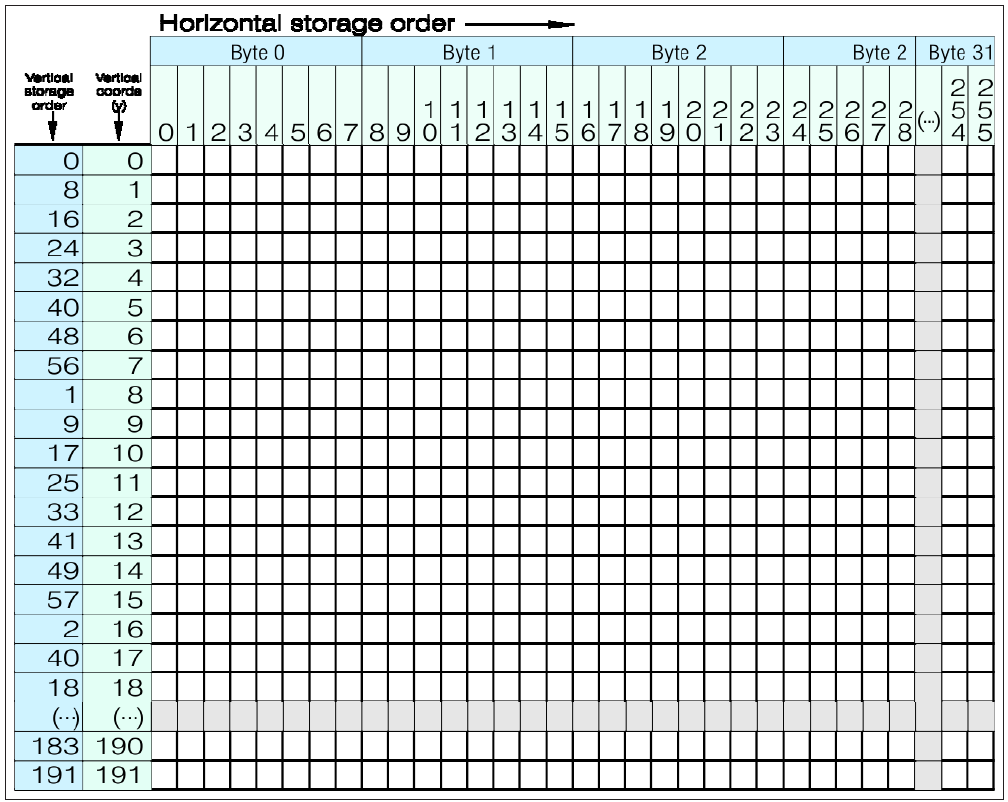
Fig. 11 – Interleaved graphic data storage for ZX Spectrum Next standard resolution Legacy modes
2 Layer 2 higher resolutions (not currently supported by NextBASIC) store things a bit differently namely in 5 vertical strips of 16K each
It's perhaps easier to understand the way things are stored by executing the following program:
10 LAYER 1,2
20 BANK 5 ERASE 0,6144,0
30 FOR %m=0 TO 6143
40 BANK 5 POKE %m,%@10101010
50 NEXT %m
This program will create vertical lines 1 pixel apart on your screen but will do so in the order they are stored in memory. As we saw previously POKE (and BANK x POKE address, value) writes a byte in memory at a specific address. The addresses we see starting with line 30 is where the screen memory is located and writing anything there will produce an image on your screen. The specific address 0 in BANK 5, marks a location called DISPLAY_FILE (or –alternatively– DISP_FILE1 but you'll see below why). It's important to note here that DISPLAY_FILE when dealing with legacy modes is always located at the same address: Byte 0 (decimal) or 0x0000 (hexadecimal) in BANK 5 (See Chapter 23 – The Memory for more details on the BANK command and its parameters).
Layer 3 differs even more on how it stores data in memory. If you recall from Chapter 14, Layer 3 is a Character Graphics mode and that name describes rather descriptively how it's arranged, in other words, very much like the screen is for regular PRINT commands as we saw in Chapter 14. The screen area is broken down to rows and columns and each of these locations, as marked by the unique row by column coordinate, points to a linearly stored 8 x 8 pixel image in memory called a tile. You can have up to 512 individual tiles in memory but you an also have as little as 1! Also the order of the tiles in memory is not important as each location can point to any tile from the ones available. In essence you can have an entire image composed of the same tile repeated over and over again much like you can fill a screen with "A" if you repeat a PRINT "A"; enough times. Layer 3 therefore is an array of pointers to the tile locations in memory. One would ask, why is this complicated mechanism necessary? The answer is quite simple and you will see it repeated further down: By using pointers (in effect indices), we can translate much larger memory structures and requirements into simpler ones, ones that an 8-bit computer like the ZX Spectrum Next can manipulate easily. We will examine Layer 3's memory organisation and usage separately and more in depth, at the end of this chapter and in the following two.
For all layers except Layer 3, the high resolution modes of Layer 2 and the Sprites Layer, the ZX Spectrum Next has a maximum horizontal resolution of 512 pixels3 and a vertical resolution of 192 pixels which gives us: 512 x 192 = 98304 pixels – or bits – in total or 12288 bytes. In order to store that, the ZX Spectrum Next defines a second DISPLAY_FILE area called DISP_FILE2 which is located at byte 8192 (decimal) or 2000h (hexadecimal) in BANK 5. This secondary area has the same organisation as the first DISPLAY_FILE but when in use it holds the display of all odd-numbered horizontal resolution addresses letting DISP_FILE1 handle the even ones.
To demonstrate this visually you will need to edit the program above as follows:
10 LAYER 1,2
20 BANK 5 ERASE 0,6144,0
30 BANK 5 ERASE 8192,6144,0
40 FOR %m=0 TO 6143
50 BANK 5 POKE %m,%@10001000
60 NEXT %m
70 FOR %x=8192 TO 8192+6143
3 The max horizontal resolution of 512 pixels is achieved by using half-width pixels which occupy the same area as the normal horizontal 256 full-width pixels.
 80 BANK 5 POKE %x,%@00100010
 90 NEXT %x
100 LAYER 0
then execute the program. The two LAYER statements first enable HiRes mode and then disable it. The two BANK 5 ERASE statements make sure there are no left over data in the DISP_FILE areas by filling them with 0s. You will see first the DISP_FILE1 area filling up and once the entire height of the screen is ran through, the DISP_FILE2 area doing the same. If you want to see this in a more dramatic way, convert line 10 to read LAYER 1,1 and then insert a line:
65 LAYER 1,2
This will illustrate even more vividly how the display is changed to handle odd and even horizontal coordinates from different areas of the memory.
So far, we learned that bits can have two states; 0 and 1; we are ready therefore to make the logical jump and assign two colour states for the image we just created. With 0 being black and 1 being white, we just defined a monochrome picture. But what about more colours?
We saw that we can display at least two colours on screen using a single bit. To display more (and store this information somewhere) we need to store more bits of information, with this information dealing exclusively with colour. In the beginning of this chapter we discussed how the ZX Spectrum Next generates and stores colour in 9 bits. The immediately obvious way to do that, would be to expand on the model displayed on Fig. 18 by adding bits in the order the ZX Spectrum Next stores them and have a linear map of 9 bits per pixel. This is a good idea but unfortunately incorrect, and the reason for that goes back to our initial discussion of the ZX Spectrum Next being an 8-bit computer making accessing 9 bits of information at a time, extremely slow and therefore impractical in terms of design, both from software and hardware standpoints.
Instead the ZX Spectrum Next uses three systems of storing and displaying colour information additionally to the HiRes mode (Layer 1,2) which we just demonstrated as the latter is monochrome so no additional colour information is needed. These are:
- Colour attribute display
- Extended colour attribute display
- Palette-based hybrid linear bitmapped colour display
Colour attribute display
This system dates from the early ZX Spectrum models and was mainly conceived to both display colour and save on memory which at the time came at a premium. The graphic display is separated in 2 areas. The first which we already showed in the previous section (DISPLAY_FILE) only holds the actual 1-bit graphic data. Size-wise and for the standard resolution of Layer 0 and Layer 1,1, this works out to: 256 x 192 = 49152 pixels – or – bits which divided by 8 gives us 6144 bytes which in turn divided by 1024 gives the 6 Kbytes figure). The second area, to which we shall introduce you now, is a smaller-sized memory block, known as COLOUR_FILE (or, alternatively, COL_FILE1) which resides immediately after DISPLAY_FILE in memory. It is 768 bytes long, and breaks down the colour information in blocks of 8 by 8 pixels (therefore dividing the screen in 32 x 24 blocks) or attribute cells where every cell can have two possible colours out of a total of 8 simultaneously. This colour information is stored in two consecutive GRB blocks of three bits each, preambled
by two additional bits that can make the colours flashing and/or brighter. Fig. 12, shows how colour information is stored in each byte in the COLOUR_FILE area.

      0     1     2     3     4     5     6     7
MSB   FL    BR    G     R     B     G     R     B    LSB
                  |--Paper Colour-| |--Ink Colour--|
Fig. 12 - Attribute byte organisation
The two colours stored within are named INK and PAPER mainly to reference the printed characters we explored in the previous chapter since INK is the colour of the character itself and PAPER is the rest of the background, in a sense a form of virtual paper we write on4. That way Layer 0 graphics can display up to 16 colours on screen using very little memory but with the tradeoff of colour clash. This term simply describes the fact that the colour resolution is much lower than the spatial one.
Like its DISPLAY_FILE counterpart, COLOUR_FILE can have a secondary area which, when enabled, is called COL_FILE2 and resides right after DISP_FILE2.
Unlike the DISPLAY_FILE areas, COLOUR_FILE areas are normally straightforward in how they are stored and that is simply in order of cells from top leftmost to right bottommost.
The secondary DISPLAY_FILE area, other than the HiRes (Layer 1,2) area for even display addresses can also function as a shadow screen which is a non-visible screen, identical in organisation to the first one, that holds a visual we may want to project quickly thus creating animation effects as we'll see in Chapter 17 – Time and Motion later on. In that usage the secondary COLOUR_FILE area functions exactly the same way as the primary one. In HiColour mode however (Layer 1,3), DISP_FILE2 becomes itself a COLOUR_FILE and the normal COL_FILE1 and COL_FILE2 are not used. It's also noteworthy, that HiRes mode also does not use the COLOUR_FILE areas but for a different reason
HiColour mode (Layer 1,3) reduces the amount of colour clash by reducing the size of attribute cells thereby extending the colour resolution to 32x192 cells of 8x1 pixels in size.
As the colour resolution increases, the memory requirements are increased as well and that is why the entire memory of DISPLAY_FILE2 is used in lieu of a COLOUR_FILE. It's easy to figure out why this happens: The original COLOUR_FILE area of 768 bytes is extended (therefore multiplied) by 8 times to make the vertical colour resolution equal to the spatial resolution. If you make the multiplication 768 x 8 you see that a further 6.144 bytes are needed to increase the colour resolution. COLOUR_FILE1 and COLOUR_FILE2 areas are unused in this mode. The organisation however of this enlarged COLOUR_FILE since the colour resolution has grown follows the one of the DISPLAY_FILE meaning that it uses the same interleaved storage as the graphic data.
We can therefore modify our original program to also display colour attributes so we can get a visual idea of the two modes' differences:
10 LAYER 1,1
20 BANK 5 ERASE 0,6912,4
30 BANK 5 ERASE 8192,6912,4
40 FOR %m=0 TO 6143
50 BANK 5 POKE %m,%@10101010
60 NEXT %m
4 This distinction is purely arbitrary but it helps distinguish these two colours from one another in a more human–readable way. They could have been easily called COLOUR_A and COLOUR_B.
 70 FOR %a=6144 TO 6144+767
 80 BANK 5 POKE
    %a,INT((RND*1)+0.2)*128 +
    %RND(128)
 90 NEXT %a
100 LAYER 1,3
110 FOR %x=8192 TO 8192+6143
120 BANK 5 POKE
    %x,INT((RND*1)+0.2)*128
    + %RND(128)
130 NEXT %x
140 LAYER 1,1
150 PAUSE 0
Lines 20 and 30 clear the DISP_FILE1 and DISP_FILE2 memory, Lines 70 to 90 fill the COL_FILE1 area with random colour information. The LAYER 1,3 command in Line 100 switches to HiColour mode and subsequently random colour information is written in each attribute cell with lines 110 to 130. As you can see, attribute cells in HiColour mode are much smaller in size and written in an interleaved manner as opposed to the linear manner demonstrated by lines 70 to 90. Finally line 140 switches back to Layer 1,1. To increase the variety of colour combinations and reduce the times of flashing being introduced the FLASH bit is randomised independently.
Extended colour attribute display
The creation of the ZX Spectrum Next brought forth Layer 2 and its extended resolutions and colours. However the need for colourisation of older software arose. What could be done to give a part of the new features to older software without breaking compatibility or having to rewrite from scratch? There have been many solutions offered since the inception of the original ZX Spectrum, each with its own strengths and drawbacks but all had been difficult, and most non-accessible in a straight forward manner from BASIC. A solution in the form of an EnhancedULA was conceived therefore that would give access to the entirety of the ZX Spectrum Next's colour capability without sacrificing compatibility or ease of use.
This is achieved by retaining the DISPLAY_FILE and COLOUR_FILE memory areas but rearranging COLOUR_FILE byte organisation by repurposing the FLASH and BRIGHT bits and increasing the amount of INK and PAPER bits which become pointers to palette colours (see the following sections for more information on palettes). This way, simple commands allow recolouring of older software which is not aware of the ZX Spectrum Next's colour 'abilities' without sacrificing compatibility. Colour clash remains (as do the attribute cell sizes) however the colour capabilities extend to a maximum of 256 colours out of the 512 the ZX Spectrum Next can display. To demonstrate (without getting into too much detail) how you can use more colours using the Extended colour attributes display of the EnhancedULA type the following program:
10 BANK NEW ba
20 FOR %a=0 TO 255
30 BANK ba POKE %a,%a
40 NEXT %a
50 LAYER 1,1
60 PALETTE DIM 8
70 LAYER PALETTE 0 BANK ba, 0
 80 PALETTE FORMAT 255
 90 BANK 5 ERASE 0,6912,255
100 %l=6144
110 REPEAT: WHILE %l<6912
120 IF %c>255 THEN %c=0
130 BANK 5 POKE %l,%c
140 %l,%c+=%1
160 REPEAT UNTIL 0
170 PAUSE 0
Don't worry about the unknown commands yet. What the program does is to create an 8-bit palette for Layer 1,1, then enable the EnhancedULA and switch it to Full Ink Mode then cycle through all 256 colours of that palette by writing in the COLOUR_FILE area the specific attribute. We'll go into more detail on how that works when we examine IN and OUT and the ZX Spectrum Next Ports System in Chapter 22
Palette-based hybrid linear bitmapped colour display
This system of colour organisation, storage and display is applicable to Layer 1,0, Layer 2, Layer 3 and partly applicable to the Sprite System. Before we explain why it's hybrid, we'll point you back to the beginning of this chapter and especially the Colour organisation and representation section. As you recall, we said there that the ZX Spectrum Next can handle both 9-bit and 8-bit colour. This is technically inaccurate as we have a broader spectrum of colours that a single byte can display.
We'll take a small detour here and explain the concept of a palette. A palette is a subset of colours where each colour displayed on screen, is not actually stored as the colour component information it's made up of, but rather as a pointer (or index) of the actual colour that's stored somewhere else. This subset in the ZX Spectrum Next's case is comprised of either 256 pointers (therefore we require only an 8-bit number to store each pointer) or 16 pointers plus one offset (therefore we require only a 4-bit number to store each pointer with an additional 4-bit number to point us to one of 16 groups of colours) to the actual colours which are represented by 16-bit numbers (therefore a set of two 8-bit consecutive numbers which have 6 bits5 unused, give the 9 bits of the actual colour stored, albeit rather inefficiently).
There are 8 palettes in the ZX Spectrum Next. Two for each graphics system:
- Layers 0 and 1 use two
- Layer 2 uses two more
- Layer 3 also uses two –and–
- The Sprite System uses the last two
With two palettes, all 512 possible colours of the ZX Spectrum Next can be recalled, rearranged and stored and therefore assigned to pixels, character tiles or attribute cells according to the layer in use, on screen. That doesn't mean all can be displayed simultaneously without some clever NextBASIC tricks. Normally only 256 can be shown on a particular layer at one time.
The ZX Spectrum Next palette system has a special mode where if one were to use an 8-bit colour in the R3G3B2 format and assign one palette in sequence to the value that equals the pointer value (for example set palette location 15 to be of a value 15) then we could treat the entire display of Layers 2 and Layer 1,0 (LoRes) as 8-bit, treating from then on the display instead of a palette-based one, as a bitmapped one. This is exactly why we can call it hybrid.
5 Obviously 16 positions minus 9 positions should equal 7 unused positions, however there's one more bit used called the 'priority bit' which although unused in the case of other layers, is used in Layer 2 palettes as we'll see in the next section.
In reality, each R3G3B2 colour is translated internally by the ZX Spectrum Next into a full RGB3 colour by performing a binary OR of the first bit (MSB) of the blue component with 0 so for example colour 10111110 (8-bit) will become internally 101111101 as a full 9-bit colour.
Layer 1,0 (LoRes) and Layer 2 are very straightforward in how they store both colour as well as graphic data. Unlike the other modes, there's no separate area for colour and there is no interleaving in the order of storage or separate pointers to the area the data is stored. Each byte of memory represents one pixel on screen from the top left to the bottom right. The only two differences between them are the memory location where the screen contents are stored and their resolution. The former uses the standard DISP_FILE1 and DISP_FILE2 areas (each holding one half of the screen) and is usually stored in BANK 5, having a maximum resolution of 128 w x 96 h pixels (thus making it a total of 12 Kbytes in size) while the latter uses up to 5 banks. The default resolution of 256 w x 192 h pixels uses normally 3 (by default BANKS 9,10 and 11 but these are relocatable6), making its memory requirements 48 Kbytes while the higher resolutions of 320 w x 256 h and 640 w x 256 h use 5 16 Kbyte banks, requiring a total of 80 Kbytes.
Although the remaining, higher resolution, Layer 2 modes are not currently supported by NextBASIC (they will however in the near future) it is important to mention them here for two reasons:
First, because they both store their data (as we will see in the last section of the following chapter) in a sideways manner and secondly because especially for the highest resolution Layer 2 mode (640 w x 256 h) the colour is stored in a similar manner as Layer 3 below.
That being said, in all Layer 2 resolutions, colour is stored as part of the graphic data and therefore neither LoRes nor Layer 2 modes suffer from colour clash.
An additional side-effect of the linear nature of these modes, is that the concepts of FLASH and BRIGHT do not exist there. BRIGHT was just a way to squeeze more colours out of a very limited selection and FLASH can be reproduced by quickly inverting the contents of an area using a number of programming techniques available via NextBASIC.
Layer 3 colour storage
Layer 3 is special as it allows for complete usage of the full Spectrum Next screen area, therefore the entirety of the 320 w x 256 h pixels resolution is available (combining the standard graphic area with the width and height of the border) and uses either (like the Sprite system we will examine in Chapter 17) a palette offset + 4-bit index combination to store colour for each tile or a monochrome mode specifically suited to display text. The first method, achieves significant memory space savings without sacrificing colour capabilities (although at first it may look a bit restrictive): Each tile being 8 x 8 has 64 possible pixel locations; by using a 4-bit colour index number we can only have 2⁴ = 16 combinations/colours instead of 64 we theoretically could have. With a bit of prior arrangement of our image data however, we can achieve spectacular results and display very complex images (colour-wise) even with that restriction in place. The monochrome mode has obvious memory benefits we have explored with Layer 1,2 (HiRes) as well as increased speed.
Layer 2 priority colours
As we will see in length on the following section, since the ZX Spectrum Next display is layered, there is a way to rearrange the layer display priority, or rather the order in which these layers are stacked one on top of another. This provides unique flexibility however there are cases that you'd want to mesh the layers in a more complex way as for example in the case of a game where you would want the player's sprite to weave in-and-out the environment in order to get the impression of depth. Usually this is achieved by employing an algorithm that performs environmental masking; hiding in other words things that we don't
6 By relocatable, we mean that although the ZX Spectrum Next initially reserves BANKS 9 through 12 for Layer 2 graphic data, this can change either automatically or by the user. One should not assume the aforementioned banks of memory always hold Layer 2 graphic data. Check Chapters 22 and 23 for more information regarding the actual Layer 2 location.
want to display on the top layer. This process, especially where it involves moving graphics, is very processor-intensive and can slow down the computer, resulting in a not-so-fluid experience of movement. The ZX Spectrum Next addresses this very specific issue with the introduction of priority colours. These apply only to Layer 2 palettes and are defined by setting the 8th bit of the secondary byte of each palette entry to 1.
Setting any palette entry's priority bit will ensure that this colour will always print on top of everything else. In case you would need the same colour to exist in a layer below the topmost you will need to define the same colour again but on a different index using the LAYER PALETTE command.
We will revisit this topic further below, when we reach the palette manipulation commands.
More on the LAYER command
In Chapter 14 as well as in the previous sections of this chapter we saw repeated mentions and usage of the LAYER command. By now, you should have enough grasp of the mechanics behind the ZX Spectrum Next's colour and graphic system to examine it in a little more detail. We will further expand on its usage every time a functionality we haven't yet discussed is introduced (as in the PALETTE section that follows shortly) but for now let's head back to the beginning of Chapter 14 and re-iterate the possible graphic modes in conjunction with LAYER which is used to change between them.
First of all and given what we've learned in terms of colour, it's helpful to conceptualise the graphic system in a slightly different manner than what the LAYER command organises them in. These layers are grouped together in terms of functionality and memory addresses they use, namely: The ULA modes (Layer 0 and all Layer 1 modes), Layer 2 and the Sprite System (which we will examine in more detail in Chapter 17 – Time and Motion). This can get a bit confusing as LoRes (Layer 1,0) and Layer 2 use the same colour storage and display system so it's better to completely disregard this and instead imagine four different screens laying on top of one another with programmable priorities and potential transparency. In simple words that means that you can select whichever screen you want to appear on top and in which order. This means putting a priority onto the memory space that holds the data for the graphics and displaying this above everything else. This is achieved with the
LAYER OVER order
command, where order is one of the following:
0 Sprites over Layer 2 over ULA (Layer 1) – the default
1 Layer 2 over Sprites over ULA (Layer 1)
2 Sprites over ULA (Layer 1) over Layer 2
3 Layer 2 over ULA (Layer 1) over Sprites
4 ULA (Layer 1) over Sprites over Layer 2
5 ULA (Layer 1) over Layer 2 over Sprites
6 Sprites over (Layer 2 + ULA combined) – colours clamped to 7
7 Sprites over (Layer 2 + ULA combined) – colours clamped to (0,7)
The last two ordinals enable one of the two colour blending modes allowing for some very interesting lighting/shading effects.
This (as we will see in Chapter 22 – IN, OUT and the Next Registers) directly affects the Sprite and Layer System Register (Register 21) and in the same order as the LAYER OVER command.
Fig. 13 below visualises the way layers compound, to form the ZX Spectrum Next display.
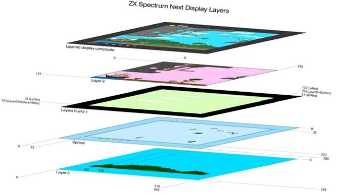
Fig. 13 – Display Layers
(Graphics courtesy of Lampros Potamianos from: The Hollow Earth Hypothesis)
You will notice a few odd things about the diagram above. First, it is out of order with the sprites appearing below Layers 0 – 2. That brings us to the second thing (don't worry the dots will be connected shortly) which is that the Sprite Layer as well as Layer 3 have a higher usable resolution than Layers 0 through 2. The order was changed to group the like resolutions ranges together and better visualise that Layer 3 as well as the Sprite System have a maximum of 320 pixel horizontal by 256 pixels vertical resolution as opposed to the 256 pixel by 192 pixel standard pixel size resolution of the other layers7. As for the order as seen in the LAYER OVER command, it really doesn't matter, as it can be rearranged in the way we see fit. In the specific example above we can see how one can mix-and-match several Layers to construct a more complex final visual; Layer 3 is used for the background, the extended sprite area for relatively static information about the game (Lives and score), LoRes (Layer 1,0) for basic parallax animation (clouds) and Layer 2 for the remaining more complex and colourful graphics.
It's also noteworthy, that although we spoke about memory organisation in regards to colour for all layers, we did not do so for the Sprite System. That is because sprites do not occupy normal memory but instead, use their own dedicated memory that's located within the Next Sprite Engine hardware. The LAYER command other than to set priorities of display does not affect, nor addresses the Sprite Engine directly therefore in the following commands, the latter is not referenced anywhere.
There are more LAYER compound commands that are more pertinent to graphics rather than colour and others that deal with motion in some fashion or other. We will revisit therefore LAYER in more detail in the following sections and chapters. The main functionality of the LAYER command which is none other than changing graphic modes.
LAYER number, parameter
will change the layer to the one specified by number with an optional parameter according to the list below:
| LAYER 0 | Select legacy ZX Spectrum Mode |
| LAYER 1,0 | Select Layer 1, LoRes mode |
| LAYER 1,1 | Select Layer 1, standard resolution mode |
| LAYER 1,2 | Select Layer 1, HiRes mode8 |
7 Layer 2 supports higher resolutions but as far as NextBASIC is concerned, currently only 256 x 192 is usable 8: HiColour and HiRes modes are also called Timex modes as they were originally introduced in the Timex Sinclair TS2068 advanced ZX Spectrum compatible computer which was released primarily for the US market in 1983.
| LAYER 1,3 | Select Layer 1, HiColour mode |
| LAYER 2 | Select Layer 2 mode |
| LAYER 2,0 | Select Layer 2 mode and disable its display |
| LAYER 2,1 | Select Layer 2 mode and enable its display |
Attempting to enter a layer number or parameter that's not supported according to this list, will result to a B Integer out of range error.
There's one more command of note and this is:
LAYER CLEAR
which will reset all layer information, including banks, mode, the Layer 2 display enable, layer offsets (see Chapter 17) and ordering to defaults. This is also done by NEW.
BORDER, PAPER, INK, BRIGHT and FLASH
Run this program:
  5 LAYER 0
 10 FOR m=0 TO 1: BRIGHT m
 20 FOR n=1 TO 10
 30 FOR c=0 TO 7
 40 PAPER c: PRINT "    ";:; 4 spaces
 50 NEXT c: NEXT n: NEXT m
 60 FOR m=0 TO 1: BRIGHT m: PAPER 7
 70 FOR c=0 TO 3
 80 INK c: PRINT c;"   ";:; 3 spaces
 90 NEXT c: PAPER 0
100 FOR c=4 TO 7
110 INK c: PRINT c;"   ";:;3 spaces
120 NEXT c: NEXT m
130 PAPER 7: INK 0: BRIGHT 0
This shows the fifteen colours (including white and black and the BRIGHT variants) that the ZX Spectrum Next can produce on the screen if switched to Layer 0 (or standard resolution modes of Layer 1) without the EnhancedULA functions enabled. Here is a list of the basic eight for reference; they are also written over the appropriate number keys on your ZX Spectrum Next's keyboard:
0 black
1 blue
2 red
3 purple –or magenta–
4 green
5 cyan –or pale blue–
6 yellow
7 white
If you're thinking to yourself that the total colours (taking account of brightness turned on) should be 16, you'd be technically right however there cannot be a BRIGHT black so the total amount of colours is indeed 15. As you've noticed, the program introduces three commands: PAPER, INK and BRIGHT. If you look back to the Colour attribute display section you will recognize the terms immediately. These commands are the primary way of applying colour to objects on screen in NextBASIC. There is a number of supporting colour commands as well which will examine further in the following sections.
Before we delve a bit deeper into what each does and how, it's very important to understand that the commands operate differently according to the layer we're on and this points back to the different way the ZX Spectrum Next stores colour. When we're dealing with modes that make use of attribute cells, we need to think in terms of those cells. PAPER there affects the background or, in other words, the place in the cell where graphic data is non existent (set to 0) whereas INK does the exact opposite and affects areas within the same cell where graphic data is existent (set to 1). Moreover these commands affect the entire attribute cell and not just one singular pixel within the cell. In other words, it doesn't matter how many times you set the INK or PAPER within a particular cell, only the last command will be the one that has the permanent effect for that cell. BRIGHT similarly affects the entire cell as we already saw, however it does absolutely nothing if EnhancedULA is enabled or if we are on modes that do not support attributes like HiRes, LoRes and Layer 2.
On LoRes and Layer2, since attribute cells do not exist, the entire notion of PAPER and INK should be irrelevant. It is easier, however, for the user to understand them in similar terms as the attribute display modes i.e. in terms of a character-based display. Indeed, there's nothing stopping us from having an 8 x 8 character drawn on screen (say a 2) with every single pixel around the character having a different colour, something that's impossible on attribute display modes. This however would be very difficult to do in terms of a singular colour command and for that reason PAPER and INK commands were simply extended to work in a similar manner as their attribute cell modes' counterparts even where their underlying mechanics are different. On the other hand, in HiRes mode, PAPER and INK commands only serve the purpose of selecting a colour scheme as we will see below. The following table shows all primary colour commands functionality according to the graphics mode we're in.
| Attribute Modes | Non-Attribute Modes | ||||||
|---|---|---|---|---|---|---|---|
| Standard ULA | EnhancedULA | ||||||
| Layer 0 | Layer 1,1 | HiColour | Layer 1,1, HiColour | HiRes | LoRes | Layer2 | |
| INK | 0-9*** | 0-7 | 0-255 | 0-7* | 0-255 | 0-255 | |
| PAPER | 0-9*** | 0-7 | 0-255 | 0-7* | 0-255 | 0-255 | |
| BORDER | 0-7 | 0-7 | 0-7** | 0-7 | 0-7 | ||
| FLASH | 0-1,8*** | 0-1 | N/A | N/A | N/A | N/A | |
| BRIGHT | 0-1,8*** | 0-1 | N/A | N/A | N/A | N/A | |
| Palette in use | ULA | ULA | ULA | ULA | L2 | ||
| * INK in HiRes is complimentary to PAPER i.e. when INK is 0 then PAPER is 7 and if INK is 3 then PAPER is 4 and so on. ** BORDER has no effect but it's set by the PAPER setting *** INK/PAPER/BRIGHT/FLASH 8 mean Transparent, ergo it preserves the colour setting that was there previously and INK/PAPER 9 mean Contrast, ie. the complimentary colour of the other statement (something similar to PAPER/INK settings for HiRes modes) | |||||||
Table 7 – Colour commands' functionality according to Graphics Mode/Layer
There is another way of using INK, PAPER etc, which you will probably find more useful than having them as statements. You can put them as items in a PRINT statement (followed by ;), and they then do exactly the same as they would have done if they had been used as statements on their own, except that their effect is only temporary: it lasts as far as the end of the PRINT statement that contains them. Thus if you type:
PRINT PAPER 6;"x";: PRINT "y"
then only the x will be on a yellow background.
When used as statements in Layer 0, INK, PAPER, BRIGHT and FLASH, do not affect the colours of the lower part of the screen, where commands and INPUT data are typed in. The lower part of the screen uses the colour of the BORDER as its PAPER colour, value 9 for contrast as its INK colour, has FLASH turned off, and everything is set at normal BRIGHT.
BORDER
Undoubtedly, you have noticed thus far, that there is an area you cannot write –normally– to, surrounding the area where you can print or draw graphics over. This area is called the BORDER and using standard NextBASIC statements you can only change its colour. The statement:
BORDER colour
changes the border colour to any of the eight normal colours (not 8 or 9) or colours changed by the PALETTE statement we shall explore below in length.
INVERSE and OVER
There are two more statements, INVERSE and OVER, which, when in an attribute mode, control not the attributes, but the actual graphic data that is printed on the screen. They use the numbers 0 for off and 1 for on in the same way as FLASH and BRIGHT do, but those are the only possibilities. If you do INVERSE 1, then the graphic data printed will be the inverse of their usual form: paper pixels will be replaced by ink pixels and vice versa.
The statement:
OVER 1
sets into action a particular sort of overprinting. Normally when something is written into a character position it completely obliterates what was there before; but now the new character will simply be added in on top of the old one (but see Exercise 1). Note that if the character you're overprinting with has a pixel in the same position with the character you're printing OVER, the result will be a blank pixel. In other words, OVER is a XOR operation.
This can be particularly useful for writing composite characters, like letters with accents on them, as in this program to print out German letters – an o with an umlaut above it:
10 OVER 1
20 FOR n=1 TO 32
30 PRINT "o"; CHR$ 8;"""";
40 NEXT n
(notice the control character CHR$ 8 which backs up one space.)
Using colour control codes
The previous example, reminded us of the PRINT positioning control codes. We can do exactly the same with colours by using the special colour control codes in a similar manner like the one we explored in Chapter 14.
The colour control codes are:
CHR$ 16 corresponds to INK
CHR$ 17 corresponds to PAPER
CHR$ 18 corresponds to FLASH
CHR$ 19 corresponds to BRIGHT
CHR$ 20 corresponds to INVERSE
CHR$ 21 corresponds to OVER
These are each followed by one character that shows a colour by its code: so (for instance):
PRINT CHR$ 16 + CHR$ 9; ...
has the same effect as:
PRINT INK 9; ...
ATTR
The ATTR function has the form:
ATTR (line, column)
Its two arguments are the line and column numbers that you would use in an AT item, and its result is a number that shows the colours and so on at the corresponding character position on the screen. You can use this as freely in expressions as you can any other function.
The number that is the result is the sum of four other numbers as follows:
128 if the character position is flashing, 0 if it is steady
64 if the character position is bright, 0 if it is normal
8 times the code for the paper colour –and finally–
the code for the ink colour
For instance, if the character position is flashing and normal with yellow paper and blue ink then the four numbers that we have to add together are 128,0,8*6=48 and 1, making 177 altogether. Test this with:
PRINT AT 0,0; FLASH 1; PAPER 6; INK 1;
" "; ATTR (0,0)
ATTR works only on Layer 0 and that is because it works by reading each COLOUR_FILE location. On different modes where the memory organisation and usage differs it will return a number that corresponds to the original COLOUR_FILE memory location, which could be for all purposes nonsense. That being said, you can get information on the extended colour attribute display if the EnhancedULA functions are enabled presuming the screen area hasn't moved. That number will correspond to the indices in use and it changes according to which PALETTE FORMAT command is in effect as we'll see below. For other modes it's safer to use the POINT TO command which we will examine in Chapter 16.
PALETTE
In previous sections of this chapter we got introduced to the subject of palettes and how they affect colour display and manipulation in each of the colour modes. We also got briefly introduced to the PALETTE keyword and a few of its uses. We can now expand a bit more on the subject, as PALETTE not only affects printing of the characters on screen but also all aspects of graphics including the ZX Spectrum Next's Sprite Engine.
The PALETTE keyword can be used as a primary statement or as a modifier to the LAYER and SPRITE statements to perform a variety of functions that pertain to colour manipulation.
As we saw, colour on the ZX Spectrum Next when using extended colour attribute display or any mode that doesn't use attributes, can be defined using 9 bits or 8 bits per colour. The default is 9; when 8 bits are chosen, as we have already seen previously, non attribute modes can emulate a straight-up bitmapped linear display (with the side-effect that only 4 levels of blue are available). In the latter case you can basically ignore all PALETTE statements as non-applicable for Layer 2 –and this whole section for that matter– however you need to use them if you want to manipulate LoRes or any of the Layer 1 and Layer 0 modes and/or change the default colours anywhere in your system, or even to recolour an old game. In order to do that and to have access to the broadest gamut of colour you will need to change the bit-depth of your palette(s). You can do so with the PALETTE DIM statement in the form:
PALETTE DIM bits
where bits can be 8 or 9.
The default colour mode of Layer 1 modes (except LoRes and HiRes) is the standard colour attribute display one. In order to enable the extended colour attribute display mode we need to enable the EnhancedULA functionality. For this you must use the PALETTE FORMAT which takes the form:
PALETTE FORMAT ink_count
where ink_count is a numerical expression specifying the number of inks to be in the palette (0,1,3,7,15,31,63,127 or 255). When the EnhancedULA is enabled, BRIGHT and FLASH are ignored, and INK and PAPER accept the appropriate new range of values. Note here that although you can specify INK and PAPER values up to 255 when writing a program, attempting to execute the program in Layer 0 will result into a K Invalid Colour error when the EnhancedULA is not enabled. To disable the EnhancedULA functionality you will need to specify an ink count of 0. The standard attributes with 8 inks, 8 papers, bright and flash are then once again supported.
As we saw in Fig. 13 there is an order of display of different layers on screen. Although it is not immediately apparent this means that it's also possible to mix display output from more than one graphical layers. That is achieved by assigning a global transparency mask for the regular layers or, in the case of the Sprites layer, a transparency index, and then colouring the areas or sprites we want to be transparent with the specific colour.
You can set the transparency colour mask or transparency colour index using the following statement:
PALETTE OVER value
where value is an 8-bit numeric expression which identifies a colour either in R3G3B2 8-bit format (in the case of regular graphics layers) or the index to the 9bit colour value we want to be transparent (in the case of the Sprites layer). The default global transparency mask and transparency colour index is light magenta / 227 (11100011 in binary).
To reset all palette data and settings to default, use the PALETTE CLEAR statement.
In the Palette-based hybrid linear bitmapped colour display section, we first discussed the existence of two palettes per display layer (note here that in this case layer is meant in the memory usage paradigm displayed in Fig. 13 so ULA layers get grouped together).
We can switch between palettes using the compound keyword:
LAYER PALETTE n
where n is the palette to use (0 or 1) for the current memory usage layer (ie. if you're in any ULA layer all of it gets affected but not Layer 2 etc).
You can point a palette for the current layer to palette data you have previously stored in memory using the following compound command:
LAYER PALETTE number BANK bank, offset
where number is the palette to update (0 or 1) for the current memory usage layer, bank is the memory bank to point to, and offset is the offset within that memory bank (For more information about BANK see Chapter 23 – The Memory).
Palette data should be either 256 double byte colour entries (for 9-bit), or 256 single byte entries (for 8-bit). As per what we discussed earlier in the chapter we need to encode the colour information in an R3G3B2 (for 8-bit) or RGB3 (for 9-bit) with every colour component value describing 8 intensities per colour.
In the double-byte entry method, the second byte in each sequence only has one bit defined for colour: the 3rd blue bit as well as one bit for priority (which only applies to palettes
used for Layer2)9. It may seem to be a bit inefficient as it stands, because it appears to be wasting memory but that's only if we store our palette in memory before we load it, otherwise palettes do not use memory at all and they only need to be set once and the memory used by the BANK method can be immediately released to the system.
You have already seen an example of this method in the Extended Colour Attribute Display System section where a palette is set up first as colours and then assigned into the chosen layer palette. Could you change it to accept double-byte colour values?
The tables that follow, show the proper format for single and double-byte palette entries. The integer values are included for a better understanding of the conversion process. In actuality, you can use either the BIN keyword or the %@ qualifier to enter binary numbers directly.
| First Byte | Second Byte | ||||||||||||||
|---|---|---|---|---|---|---|---|---|---|---|---|---|---|---|---|
| R₁ | R₂ | R₃ | G₁ | G₂ | G₃ | B₁ | B₂ | P2 | 0 | 0 | 0 | 0 | 0 | 0 | B₃ |
| 128 | 64 | 32 | 16 | 8 | 4 | 2 | 1 | 0 | 0 | 0 | 0 | 0 | 0 | 0 | 1 |
| 4 | 2 | 1 | 4 | 2 | 1 | 2 | 1 | 0 | 0 | 0 | 0 | 0 | 0 | 0 | 1 |
| 7 | 6 | 5 | 4 | 3 | 2 | 1 | 0 | 7 | 6 | 5 | 4 | 3 | 2 | 1 | 0 |
Table 8– Double byte colour entry
| First Byte | |||||||
|---|---|---|---|---|---|---|---|
| R₁ | R₂ | R₃ | G₁ | G₂ | G₃ | B₁ | B₂ |
| 128 | 64 | 32 | 16 | 8 | 4 | 2 | 1 |
| 4 | 2 | 1 | 4 | 2 | 1 | 2 | 1 |
| 7 | 6 | 5 | 4 | 3 | 2 | 1 | 0 |
Table 9 – Single byte colour entry
Writing the entire palette into memory is not the only option available to the user in order to program a palette. It is also possible to specify individual colours within the palette using the following compound command (as with the rest of the examples in this section layer here implies a memory space organisational unit):
LAYER PALETTE number, index, value
where number is the current layer palette we wish to update (0 or 1), index is the index of the palette entry to be updated (0 to 255), and value is the colour components value expressed in binary using either the BIN keyword or the %@ qualifier in RGB3 format. That means that the colour in that case is ALWAYS 9-bit For example:
LAYER PALETTE 0,0,BIN 110010011
that sets colour index 0 in palette 0 to a nice pink is exactly the same as:
LAYER PALETTE 0,0,%@110010011
Exercises
-
Try:
PRINT "B"; CHR$ 8; OVER 1; "/"Where the / has cut through the B, it has left a white dot. This is the way overprinting works on the ZX Spectrum: two papers or two inks give a paper, one of each gives an ink. This has the interesting property that if you overprint with the same thing twice you get back what you started off with. If you now type:
9 In the future 15-bit (with priority) or even 16-bit (without priority) may be possible on an HDMI display as the hardware is very capable of displaying it albeit slowly
PRINT CHR$ 8; OVER 1; "/"
Why do you recover an unblemished B?
-
Type:
PAPER 0: INK 0Isn't it just as well that these don't affect the lower part of the screen?
Now type:BORDER 0and see how well the computer looks after you!
But what will happen if you do the same after giving:LAYER 1,3 -
Run this program:
10  POKE 22527+RND*704, RND*127
20  GO TO 10
Never mind how this works; it is changing the colours of squares on the screen and the RNDs should ensure that this happens randomly. The diagonal stripes that you eventually see are a manifestation of the hidden pattern in RND – the pattern that makes it pseudorandom instead of truly random.
-
Type in the chess piece characters in Chapter 13 and then type in this program which draws a diagram of chess positions using them:
5  REM draw blank board
10 bb,bw=1,2: REM red and
   blue for board
15 PAPER bw: INK bb: CLS
20 PLOT 79,128: REM border
30 DRAW 65,0: DRAW 0,-65
40 DRAW -65,0: DRAW 0,65
50 PAPER bb
60 REM board
70 FOR n=0 TO 3: FOR m=0 TO 3
80 PRINT AT 6+2*n, 11+2*m;"  "
90 PRINT AT 7+2*n, 10+2*m;"  "
100 NEXT m: NEXT n
110 PAPER 8
120 pw,pb=6,5: REM colours of
     white and black pieces
200 DIM b$(8,8): REM positions of pieces
205 REM set up initial positions
210 b$(1)="rnbqkbnr"
220 b$(2)="pppppppp"
230 b$(7)="PPPPPPPP"
240 b$(8)="RNBQKBNR"
300 REM display board
310 FOR n=1 TO 8: FOR m=1 TO 8
320 bc=CODE b$(n,m): INK pw
325 IF bc=CODE " " THEN GO TO 350
    : REM   space
330 IF bc>CODE "Z" THEN INK pb:
     bc-=32:;lowercase for
    black
340 bc+=79:;convert to
    graphics
350 PRINT AT 5+n, 9+m; CHR$ bc
360 NEXT m: NEXT n
400 PAPER 7: INK 0
-
The program in p. 86 has a non-apparent flaw. Can you improve on it so it becomes faster?
-
Write a version of ATTR using a PROCedure that will work always, no matter the mode. You can peek ahead if you so wish!
-
Using the global transparency colour, palettes and layers can you write a program that will display ALL 512 colours of the ZX Spectrum Next on screen? (It's easier than you think)
ZX Spectrum Next User Manual, 3rd Edition (ISBN 978-1-5272-5496-1), written and illustrated by Phoebus R. Dokos. Copyright © 2020-2024 Phoebus Dokos / SpecNext Ltd. Licensed under CC BY-NC-SA 4.0. This is a transcription and can contain errors; check any doubt against the printed page.