a gross simplification) but both how many dots and how many colours we can fit. The former is spatial resolution (it has one more component; density but this is not pertinent to this discussion) and the latter, colour resolution. It's important to make the distinction as we will see below because this informs not only a computer's design choices when it comes to graphics but also the special trickery that may be involved to display both on screen.
It's easy to understand spatial resolution. We –as you already read here and probably elsewhere– measure spatial resolution in pixels –or PICTure ELements–, in essence dots arranged in a Cartesian, two-dimensional coordinate system. Leaving colour information aside for the moment we can assign one bit per pixel and we can project this in the computer's memory in a linear fashion: Each horizontal line, follows the other so in the end we have a series of bits with each line being w x n times away from the very first bit that started our picture where w is our horizontal resolution and n is the line we're on. We need w x h bits to represent our screen spatially, where w is as before the horizontal size and h is the vertical size (both of them measured in pixels).
This is very straightforward and indeed the ZX Spectrum Next uses this way to store graphic data on Layers 22 and Layer 1,0. However in all the older modes, it uses a variation of linear storage called interleaved storage. The screen area is separated vertically into three 64 pixel high strips (or 8 attribute cells) arranged in blocks of 32. Each complete line (x) is stored linearly; in other words a pixel stored in horizontal coordinate 9 follows the pixel stored in horizontal coordinate 8 however, when it comes to the vertical order, there is a virtual hopscotch of sorts happening: The computer stores the first line of the first block of attribute cells, then stores the first line of the second block until it reaches the first line of the 8th block, then returns to the second line of the first block and the order continues with all second lines, then thirds and so on, until each third of the screen is full. Fig.19 demonstrates the order of storage for ZX Spectrum Next legacy modes in order to visualise it a little better. We will get into more detail on why the graphic data is stored in that way later.
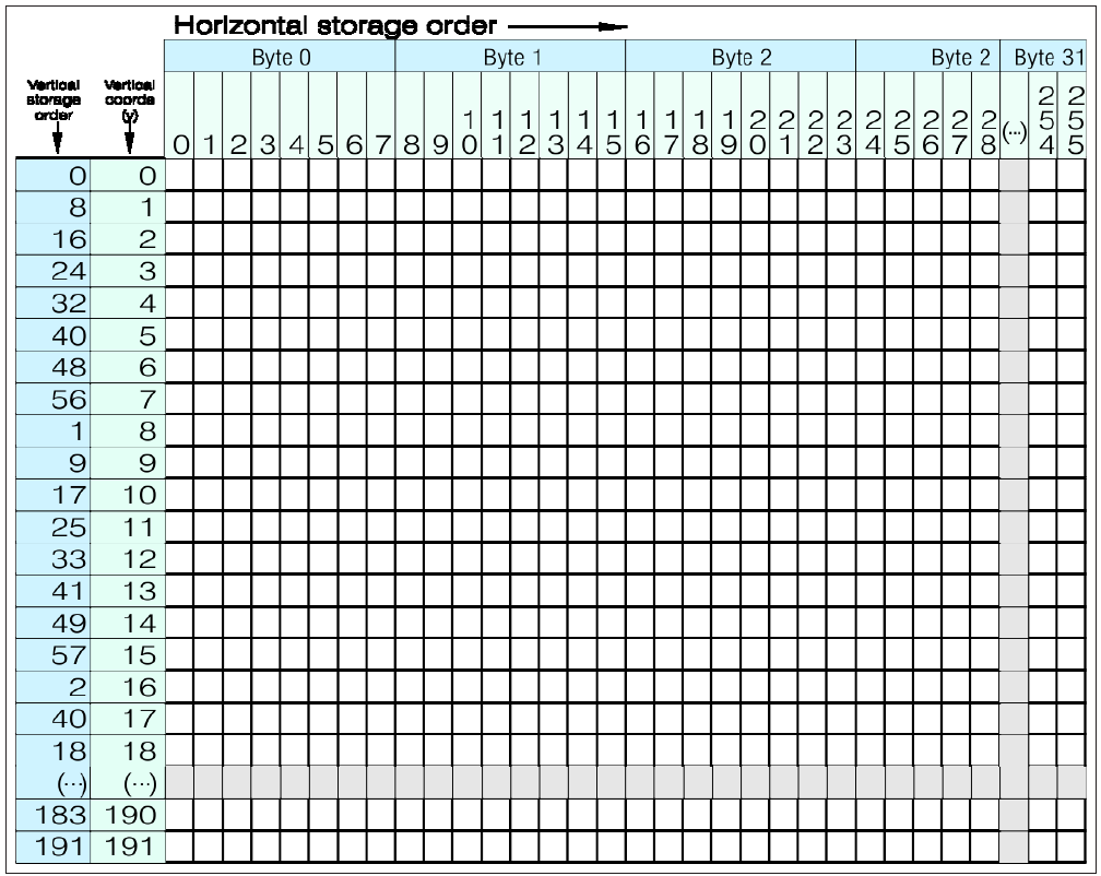
Fig. 11 – Interleaved graphic data storage for ZX Spectrum Next standard resolution Legacy modes
2 Layer 2 higher resolutions (not currently supported by NextBASIC) store things a bit differently namely in 5 vertical strips of 16K each
ZX Spectrum Next User Manual, 3rd Edition (ISBN 978-1-5272-5496-1), written and illustrated by Phoebus R. Dokos. Copyright © 2020-2024 Phoebus Dokos / SpecNext Ltd. Licensed under CC BY-NC-SA 4.0. This is a transcription and can contain errors; check any doubt against the printed page.