every other module) make sure you provide enough support on the obverse so the board doesn't flex. Refer to the figure below on the proper installation of each RAM chip.
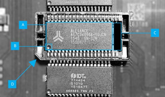
Fig. 34 – Optional RAM upgrade installed
The Raspberry Pi Zero (RPi0) accelerator requires a little bit of work. You will need to solder the 40 pin (2 x 20) FEMALE IDC header on the RPi0's GPIO through-holes. Unlike what would be normally expected the socket needs to be soldered from the component side, therefore facing downwards. With a properly soldered IDC header you need to be able to see the RPi0's SD card reader and all its components with the IDC header out of view like in the figure below:
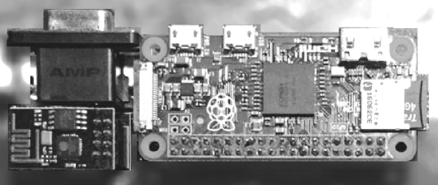
Fig. 35 – Raspberry Pi 0 installed on Issue 2 board (with WiFi module in view - left)
Please note that there is a backplate inside the case covering the holes of where the RPi0's USB, Power and Video out will have to appear from. Remove its screws and then pry it out gently with a flat screwdriver before attempting reassembly. Also pay attention to the Quick Start note regarding what is allowed to be plugged in the RPi0!!! This is also an ideal time to remove the expansion port backplate/cover if you plan on using your ZX Spectrum Next with external interfaces. Figure 36 shows how a ZX Spectrum Next looks disassembled and there's special mention of both backplates.
The most complicated installation is that of the RTC module. It requires you to solder the oscillator in the X1 location of the board, a battery holder in the location marked and finally the DS1307 IC in its place next to the battery holder paying attention to the orientation (marked by a notch on the sketch on the board as well as on the chip itself). It's advisable that you install a 8 pin DIL socket instead of the DS1307 IC as heat may damage it during soldering.
You should exercise caution while soldering the oscillator; the through holes are very small and need to be free of any flux or solder residue as this will stop the oscillator from working. Finally, you will need to install the battery in the socket otherwise the RTC will only work for as long as the machine is powered.
ZX Spectrum Next User Manual, 3rd Edition (ISBN 978-1-5272-5496-1), written and illustrated by Phoebus R. Dokos. Copyright © 2020-2024 Phoebus Dokos / SpecNext Ltd. Licensed under CC BY-NC-SA 4.0. This is a transcription and can contain errors; check any doubt against the printed page.