Pages 220–228 · Markdown
Chapter 21 – Optional Features
Overview
Depending on the model you have and the Kickstarter you participated in, your ZX Spectrum Next may have one of two types of mainboards; Issue 2 or Issue 4 (See appropriate figures in the beginning of this Chapter). If you have an Issue 2, the rest of the chapter is for you, as many of the standard features on an Issue 4, used to be optional on the Issue 2. These are: RTC hardware, a WiFi module (ESP), extra RAM and the Raspberry Pi Zero (RPi0) accelerator.
If on the other hand, you have an Issue 4, the only feature you may be interested in is the Raspberry Pi Zero accelerator. The following sections will describe how to install and use them. Remember that modifying your ZX Spectrum Next carries a number of risks and that if you are not careful, you can damage your machine!
Notes
⚠
Before you proceed, please make sure that:
A. You're comfortable with tools and at least somewhat dexterous with a soldering iron
B. You understand the dangers of Electrostatic Discharge and sensitive components
C. You have enough patience –and finally–
D. You have downloaded and installed the latest System/Next™ distribution
Installation (for Issue 2 mainboards)
Most add-ons are very easy to install with the exception of the Real Time Clock module and RPi0 accelerator. Installation of the former, requires soldering a number of parts onto the board and should be undertaken only by users with soldering experience. We recommend using a specialised service, if you do not feel comfortable with a soldering iron. Installation of the latter also requires soldering experience but that's confined on the RPi0 board itself and not on the ZX Spectrum Next. On the table below, we list all parts that you will need to perform each upgrade:
| Option | Parts Needed | Notes |
|---|---|---|
| 1024K Memory upgrade | 2 x Alliance AS7C34096A-10JCN –or– 2 x Samsung K6R4008V1D-JI10 |
Upgrades the memory to 2048K |
| RTC module | 1 x DS1307 IC 1 x YXC YT-38, 32.768KHZ, 12pF oscillator or similar 1 x CR2032 Battery holder 1 x CR2032 Battery 3.3V 1 x 8 pin DIL socket (optional) |
Allows time and date keeping that does not rely on your computer being powered on |
| WiFi module | ESP8266 ESP-01 | Provides access to the internet and your home network |
| RPi Accelerator | 1 x Raspberry Pi Zero 1 x Female IDC connector 2 x 20 pins |
Various functions such as enhanced audio |
Installing a WiFi module, only requires you to populate the empty socket marked by a B on the diagram (page 218) by plugging in the ESP module in the place reserved.
Memory is equally simple, however, care must be exercised in that the RAM sockets accept larger chips than the ones the ZX Spectrum Next has. You need to line up the orientation notch (B) of each RAM chip (A) with the corner of the socket (D) leaving space (C) in the back of the socket. Once you have everything lined up, push with your finger at the centre of the RAM chip and it should make a slight click. While pushing the RAM in (and
every other module) make sure you provide enough support on the obverse so the board doesn't flex. Refer to the figure below on the proper installation of each RAM chip.
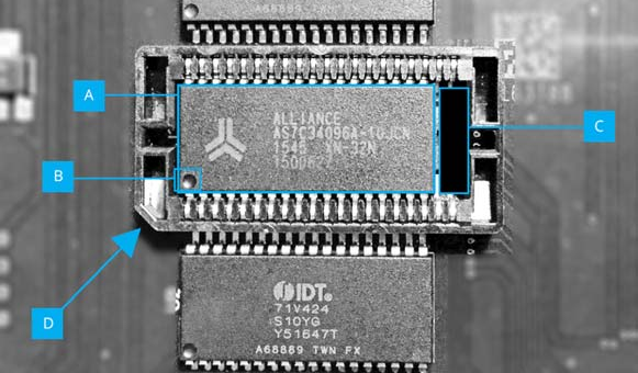
Fig. 34 – Optional RAM upgrade installed
The Raspberry Pi Zero (RPi0) accelerator requires a little bit of work. You will need to solder the 40 pin (2 x 20) FEMALE IDC header on the RPi0's GPIO through-holes. Unlike what would be normally expected the socket needs to be soldered from the component side, therefore facing downwards. With a properly soldered IDC header you need to be able to see the RPi0's SD card reader and all its components with the IDC header out of view like in the figure below:
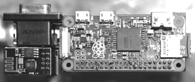
Fig. 35 – Raspberry Pi 0 installed on Issue 2 board (with WiFi module in view - left)
Please note that there is a backplate inside the case covering the holes of where the RPi0's USB, Power and Video out will have to appear from. Remove its screws and then pry it out gently with a flat screwdriver before attempting reassembly. Also pay attention to the Quick Start note regarding what is allowed to be plugged in the RPi0!!! This is also an ideal time to remove the expansion port backplate/cover if you plan on using your ZX Spectrum Next with external interfaces. Figure 36 shows how a ZX Spectrum Next looks disassembled and there's special mention of both backplates.
The most complicated installation is that of the RTC module. It requires you to solder the oscillator in the X1 location of the board, a battery holder in the location marked and finally the DS1307 IC in its place next to the battery holder paying attention to the orientation (marked by a notch on the sketch on the board as well as on the chip itself). It's advisable that you install a 8 pin DIL socket instead of the DS1307 IC as heat may damage it during soldering.
You should exercise caution while soldering the oscillator; the through holes are very small and need to be free of any flux or solder residue as this will stop the oscillator from working. Finally, you will need to install the battery in the socket otherwise the RTC will only work for as long as the machine is powered.
Raspberry Pi Zero installation on the Issue 4 mainboard
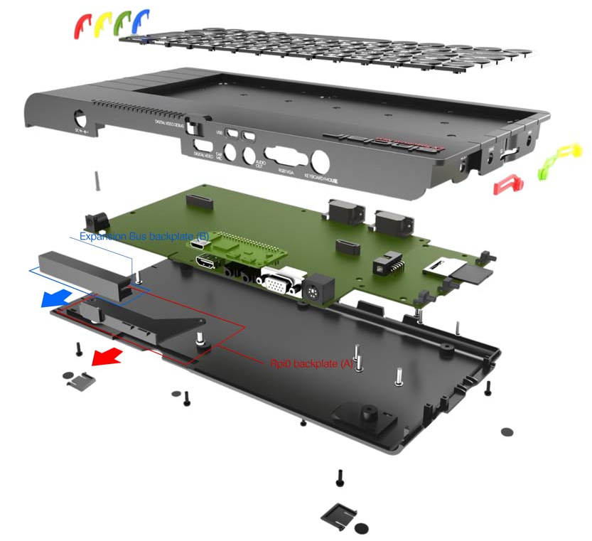
Expansion Bus backplate (B)
Rpi0 backplate (A)
Fig. 36 – Disassembled Next. Note the expansion port and Raspberry Pi 0 backplates
The RPi0 installation on the Issue 4 mainboard does not differ in any way from the one done for the Issue 2. So if you don't have an Accelerated Next, follow the instructions in the previous section as they apply here as well.
Notes
⚠
The diagram above (Fig. 36) shows a completely disassembled ZX Spectrum Next computer for illustrative purposes only. Not everything can be disassembled; the keyboard itself is considered a standalone unit, fastened onto the top of the case by 10 M3 x 4mm screws and YOU SHOULD NOT ATTEMPT TO DISASSEMBLE IT!!!
USER DISASSEMBLY of the Keyboard unit will NOT be supported by SpecNext Ltd and will invalidate the warranty!
Testing the add-ons' installation
Once you have your add-ons installed, it is time to test them; we'll start with the easier tests first and we'll progress to the most difficult ones.
A. Testing the memory
This is by far the simplest test; if your memory installation worked, your NextZXOS Startup menu will report 1792K instead of the 768K it reported up until now (see Fig. 37).
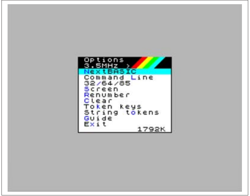
Options
3.5MHz  >
NextBASIC
Command Line
32/64/85
Screen
Renumber
Clear
Token keys
String tokens
Guide
Exit                1792K
Fig. 37 – NextZXOS Options menu showing 2MB
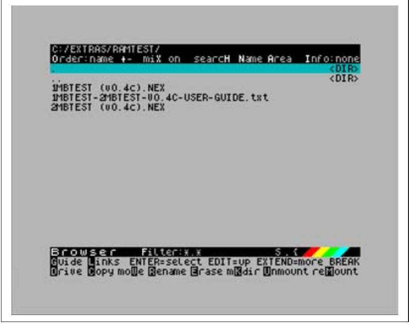
To further verify that the memory was properly installed, there's a program called 2MBTEST (v0.4c).nex located under c:/extras/memtest in your System/Next™ distribution.
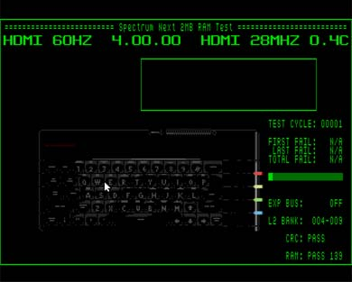
Execute it with the browser or by using the .nexload dot command and let it go through all your memory testing it's working properly (see Fig. 38 and 39).
C:/EXTRAS/RAMTEST/
Order:name +-  miX on  searcH Name Area  Info:none
.                                                  <DIR>
..                                                 <DIR>
1MBTEST (v0.4c).NEX
1MBTEST-2MBTEST-U0.4C-USER-GUIDE.txt
2MBTEST (v0.4c).NEX


Browser    Filter:*.*                        S.[?]
Guide Links  ENTER=select EDIT=up EXTEND=more BREAK
Drive Copy moVe Rename Erase mKdir Unmount reMount
Fig. 38 – Using the browser to launch 2MBTEST
==================== Spectrum Next 2MB RAM Test ====================
HDMI 60HZ   4.00.00   HDMI 28MHZ 0.4C


                                            TEST CYCLE: 00001

                                            FIRST FAIL:  N/A
                                             LAST FAIL:  N/A
                                            TOTAL FAIL:  N/A

                                            EXP BUS:      OFF
                                            L2 BANK:  004-009

                                            CRC: PASS

                                            RAM: PASS 139
Fig. 39 – 2MBTEST running without faults so far
In case that something went wrong, your memory chips are either defective or you didn't install them properly. Make sure your memory chips are properly seated in their sockets by a. checking the space is left as in Fig. 34 and b. pressing them firmly in their socket until you hear a subtle "click" sound. If the memory test still fails, your memory chips are probably defective.
B. Testing the WiFi
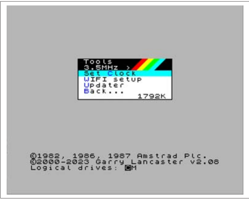
Testing the WiFi feature is a very simple procedure. You only need to use NextZXOS Startup Menu, go under Tools and then select WIFI setup.
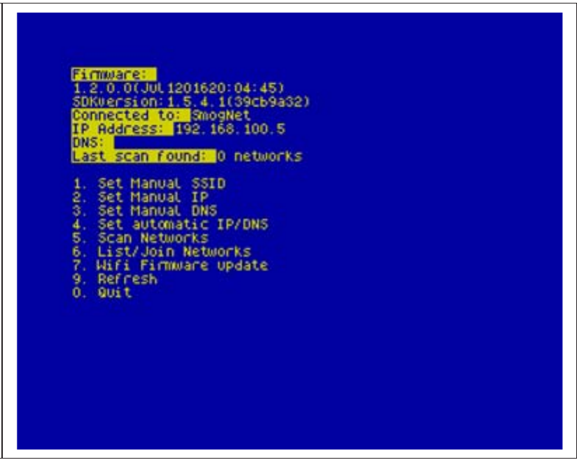
As seen in the figures below, you only have to select option 5 (Scan Networks) and once your network is found, you enter the password and that was all!
In case this does not work and you have still questions whether or if your WIFI module is really problematic, you can use the .uart dot command from your System/Next™ distribution.
Tools
3.5MHz  >
Set Clock
WIFI setup
Updater
Back...             1792K


©1982, 1986, 1987 Amstrad Plc.
©2000-2023 Garry Lancaster v2.08
Logical drives: CM
Fig. 40 – NextZXOS Tools submenu
Firmware:
1.2.0.0(Jul 1201620:04:45)
SDKversion:1.5.4.1(39cb9a32)
Connected to: SmogNet
IP Address: 192.168.100.5
DNS:
Last scan found: 0 networks

1. Set Manual SSID
2. Set Manual IP
3. Set Manual DNS
4. Set automatic IP/DNS
5. Scan Networks
6. List/Join Networks
7. Wifi Firmware update
9. Refresh
0. Quit
Fig. 41 – WIFI setup program
.uart is not very complicated but it's quite temperamental especially if you use a PS/2 keyboard. You will need to use the standard ZX Spectrum keys; CAPS SHIFT + 0 for DELETE, SYMBOL SHIFT + K for +, SYMBOL SHIFT + C for ?, SYMBOL SHIFT + P for ", SYMBOL SHIFT + N for , and SYMBOL SHIFT + L for =.
You run it by issuing a:
.uart
you will be greeted by a screen full of information that will end in an L cursor. To test type the following:
AT
and press ENTER
If you're good so far, the ESP will be responding with:
OK
That's a very good sign. That means serial communications have been established. To see however if the ESP is actually working you'll need to issue a few more commands. Type:
AT+CWMODE?
the ESP there should respond with a 1, 2 or 3 (this is the mode that's its working at; being 1 for Station, 2 for Access Point and 3 for both). Normally this should be enough to verify your ESP is working but if you want to take it one step further, you should set the ESP to station mode by giving:
AT+CWMODE=1
then check for what Access Points are around by doing:
AT+CWLAP
before finally connecting to one by giving the command:
AT+CWJAP="SSID","YourPass"
where SSID is the name of your network and YourPass is your WiFi password. The ESP will retain these so you can do if you want:
AT+RST
which will reset your ESP and give you a lot of information before concluding with a
WIFI CONNECTED
WIFI GOT IP
Exit .uart by pressing SYMBOL SHIFT + SPACE. If none of this worked, then the most likely culprits are that you either have a bad ESP module or that the power supply you're using is not powerful enough for both your ZX Spectrum Next and the ESP module. First try with a different power supply, otherwise return the ESP module for an exchange.
Note that different ESP firmware versions have slightly different versions of the commands above so always consult the most up-to-date documentation!
C. Testing the RTC installation
There are several ways of testing if the RTC was properly installed the easiest of which is to launch again the NextZXOS Startup Menu and then go to the Tools Submenu. There apart from the WIFI setup option, you will find a Set Clock option. Launching it will allow you to program your RTC using just your cursor and the ENTER keys:
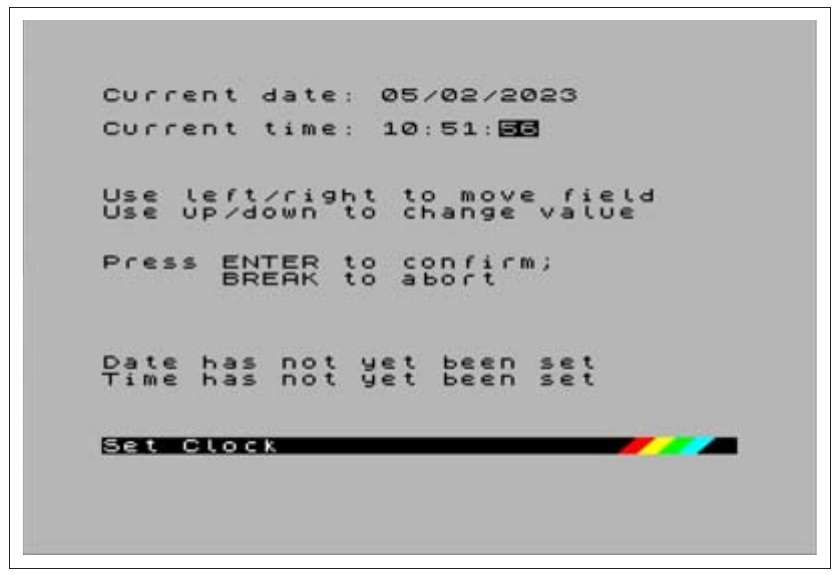
Current date: 05/02/2023
Current time: 10:51:56

Use left/right to move field
Use up/down to change value

Press ENTER to confirm;
      BREAK to abort

Date has not yet been set
Time has not yet been set

Set Clock
Fig. 42 – NextZXOS Set Clock utility
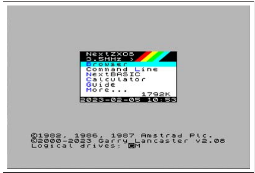
If everything worked right, then NextZXOS shall start reporting the current time and date on its menus like so:
NextZXOS
3.5MHz  >
Browser
Command Line
NextBASIC
Calculator
Guide
More...              1792K
2023-02-05 10:53

©1982, 1986, 1987 Amstrad Plc.
©2000-2023 Garry Lancaster v2.08
Logical drives: CM
Fig. 43 – RTC Working
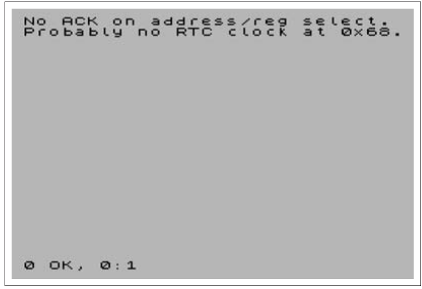
If however the clock won't work, there's a very simple way of testing for the RTC and that's to give it the .time command. If it doesn't work outright, it will produce an output like the one shown in Fig. 44.
There are a few issues that can occur with the RTC; if the output is as above, the most likely culprit is the soldering of the IC onto the board. A cold solder will leave the RTC not working, a short somewhere will do the same but the RTC IC will start getting hot. If you feel the IC warming up disconnect all power immediately and inspect your soldering.
A defective battery holder installation as well as a defective (or depleted) battery will manifest itself with the RTC not keeping time upon bootup and NextZXOS not displaying the time and date information on its Startup Menu. Setting the time and date anew, however, will restore the time display.
No ACK on address/reg select.
Probably no RTC clock at 0x68.


0 OK, 0:1
Fig. 44 – RTC not working
If on the other hand the commands described in the Using the Real Time Clock hardware section below do work, the time and date information appear in the Startup menu but time does not advance, then the issue lays usually with either the oscillator or the pins of the DS1307 IC these connect to. There's either a short somewhere or even a situation as simple as leftover flux from soldering. The oscillator can be damaged quite easily so make sure there's no continuity on its two legs before even turning the power on and inserting the battery in the holder.
D. Testing the Accelerator installation
Before you can test that the accelerator is working, there are a few things you need to do: First find a 16 Gb or larger microSD Card and then you need to download the NextPi2 distribution from: http://zx.xalior.com/NextPi2 together with the instructions that accompany it.
Once you prepare the SD card according to the instructions, put it in your Pi Accelerator prior to booting up your ZX Spectrum Next. The Pi support programs are already in the c:/apps/rpi folder on your System/Next™ distribution's SD, so you do not need to do anything else other than powering up the machine.
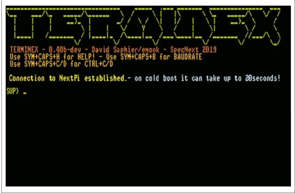
If you have access to the RPi0 you should see the green led flashing while the ZX Spectrum Next is booting; that's a good first sign showing that the RPi0 is loading its NextPi2 distribution. The LED will eventually stop flashing and should turn into a steady green. Once you're all booted up, change to the NextPi2 support folder, switch to the terminex folder and execute (with the browser or with the SPECTRUM command) terminex.snx by David Saphier. If the RPi0 installation worked, you will see a message stating Connection to NextPi established followed by a SUP> prompt which means your RPi0 installation was successful as shown in the figure below.
TERMINEX

TERMINEX - 0.40b-dev - David Saphier/emook - SpecNext 2019
Use SYM+CAPS+H for HELP! - Use SYM+CAPS+B for BAUDRATE
Use SYM+CAPS+C/D for CTRL+C/D

Connection to NextPi established.- on cold boot it can take up to 20seconds!

SUP> _
Fig. 45 – RPi Supervisor prompt via Terminex
If the SUP> prompt does not appear after a maximum of 20-25 seconds, that means there's something wrong. That doesn't mean your RPi0 is not working; especially if you saw the flashing green LED light on it earlier. This more than likely means that you didn't transfer the NextPI2 image properly or that there's some problem with the microSD card you used.
To verify the RPi0 is working, you will need to unplug it from your ZX Spectrum Next, locate a micro usb power supply, an appropriate HDMI™ cable and a standard RPi0 distribution and power it independently.
If you can see output on the screen, then there's either a problem with your NextPI2 SD card (which you can verify by plugging its microSD card in the RPi0's reader instead of the standard RPi0 distribution), a cold solder on your IDC connector you soldered earlier, or finally, an insufficiently powerful, power supply for your ZX Spectrum Next.
The RPi0s are very resilient pieces of hardware and they don't fail easily; chances are any failure you experience is due to one of the cases listed.
Using the Real Time Clock hardware
If you're lucky to have an expanded ZX Spectrum Next with the battery backed-up Real Time Clock (RTC) hardware installed (or if you followed the instructions to install it yourselves) then more options in timekeeping become available to you. These options do not suffer from the drawbacks and caveats laid out in the previous sections as this dedicated hardware option keeps time regardless of what else the computer is doing and in fact keeps time even when the computer is turned off.
The RTC is accessible via the function TIME$ (See Chapter 17) as well as two dot commands: .date and .time.
Setting up your RTC for first use
As we saw above, invoking the Set Clock option found in the Tools submenu of the NextZXOS Startup Menu has the obvious benefit of setting up the clock AND testing at the same time. There are however two more ways to set your RTC up, especially if for some reason you wish to use an alternative to NextZXOS like for example esxDOS.
Using .time and .date
This is very straightforward with the small exception that before you can use .date and .time you will need to set up your Real Time Clock hardware. Luckily this is only done once when you install it and whenever you need to change battery. You will initially (for safety) need to issue the command:
.time -di
This wipes the RTC signature from the chip and gets it ready to accept a date and time. You can then type:
.time "10:35:23"
where "10:35:23" can be substituted by any string of the format HH:MM:SS where HH (hour) is a number from 00 to 23 , MM (minute) is a number from 00 to 59 and SS (second) is a number from 00 to 59. You then enter the correct date by issuing:
.date "20/03/2023"
where "20/03/2023" can be substituted by any string of the format DD/MM/YYYY where DD is the day (01 to 31), MM is the month (01 to 12) and YYYY is any year from 2000 to 2099.
A few interesting things will happen once you install and setup your RTC. First, NextZXOS will report the time and date on its Startup menu (which is very nice indeed). Then, your saved files will start having a date and timestamp on them (visible with CAT EXP or .ls).
Using the RTC together with the WiFi module
The RTC module is not very accurate and can lose several seconds over the period of a few weeks. Luckily, like other, much larger systems, the ZX Spectrum Next can also set its time from the internet, thanks to .nxtp, the dot command client to Robin Verhagen-Guest's NeXt Time Protocol server. Its syntax is:
.nxtp server-address port [-z=Timezone]
where server-address is a FQDN or IP address running a nxtp server, port is the port where that nxtp server is listening to (by default 12300) and an optional timezone parameter to set the time to any location you would like from a list of acceptable timezones.
.nxtp time.zx.in.net 12300 -z=UTC
will talk to the the nxtp server located at time.zx.in.net, listening on port 12300 and set the RTC's time to Coordinated Universal Time (UTC) whereas
.nxtp time.zx.in.net 12300 -z=GMT
will do the same but for Greenwich Mean Time meaning the time will adjust for summer giving you BST and winter giving you UTC, as .nxtp already knows about daylight savings. It will work this into your RTC's time setting meaning you never have to worry about setting your clock in the summer or winter provided your location observes these.
A full list of accepted timezones exists at the .nxtp project's wiki page located at: https://github.com/Threetwosevensixseven/nxtp/wiki/Timezone-Codes
It is a good idea, if you have an always working WiFi setup, to add .nxtp to your autoexec.bas file so it always sets the correct time whenever your ZX Spectrum Next boots. The potential startup delay is very small and the benefit of always having correct time outweighs the delay.
Using the rest of the add-ons
Both the WiFi and Raspberry Pi Accelerator add-ons open up exciting features not before seen on a ZX Spectrum computer. This chapter provides only limited coverage as the feature set of both is still evolving. We have included all features implemented thus far (Audio playback, TZX loading, DRIVER support etc) in Chapters 18, 19, 20 and this chapter, however, you're encouraged to read the accompanying documentation found in your System/Next™ distribution and on www.specnext.com as they will always contain the most up-to-date information regarding these add-ons and newer ZX Spectrum Next features.
ZX Spectrum Next User Manual, 3rd Edition (ISBN 978-1-5272-5496-1), written and illustrated by Phoebus R. Dokos. Copyright © 2020-2024 Phoebus Dokos / SpecNext Ltd. Licensed under CC BY-NC-SA 4.0. This is a transcription and can contain errors; check any doubt against the printed page.