Pages 121–143 · Markdown
Chapter 17 – Time and Motion
One of the most important features of the ZX Spectrum Next is the ability to move things on screen fast, either via the usage of sprites or by quickly interchanging full screens to create animations and general visual effects. Motion (and animation) however, as on real life, is a function of time. In other words we need to precisely count time in order to display things and for this purpose this chapter will deal with these two seemingly unrelated subjects in one unit. We will begin with the whole idea of timekeeping on the computer and all the facilities the ZX Spectrum Next has in order for us to measure time.
Timekeeping is essential in computing as all devices work on the basis of a unit of time (in our case Hertz –or– Hz) but much of this happens behind the scenes. Here we will examine commands related to time together with the optional timing hardware, before we move into animation, scrolling, the Sprite Engine and eventually to the Copper.
PAUSE
While the general attitude in programming is to make things execute as fast as possible, we often find ourselves in need of making our program wait for a specific length of time or even indefinitely. There is a number of reasons why that would be the case; expecting user interaction is one; displaying warnings is another, timing precisely something is a third and for all the above and more you will find the PAUSE statement useful.
PAUSE n
stops computing and displays the picture for n frames of the selected display mode.
In 50Hz mode, there are 50 frames-per-second (fps), so setting n to 50 would result in 1 sec. pause. Respectively in 60Hz mode which runs at 60 fps this figure would be 60 for 1 sec. pause.
These modes are set these at the Configuration boot menu or via the config.ini file which is located in the c:/machines/next/ folder. Generally speaking, almost all modern HDMI™ and VGA displays operate at 60Hz, while many also have 50Hz modes.
n can be up to 65535, which gives you just a little over 21 minutes at 50Hz and just under 19 minutes at 60Hz respectively; if n is set to 0 then it means PAUSE indefinitely.
A pause of any length (including the indefinite ones) can always be cut short by pressing a key (note that CAPS SHIFT + Space or BREAK will cause a break as well). You have to press the key down after the pause has started.
This program works the second hand of a clock:
 10 REM We select the appropriate
    pause
 20 wait=52:REM 50Hz/50=1 sec.
 30 REM First we draw the clock face
 40 FOR n=1 TO 12
 50 PRINT AT 10-10*COS(n/6*PI),
    16+10*SIN(n/6*PI);n
 60 NEXT n
 70 REM Now we start the clock
 80 FOR t=0 TO 200000: REM t is the
    time in seconds
 90 a=t/30*PI : REM a is the angle of
    the second hand in rad.
100 sx,sy=80*SIN a,80*COS a
200 PLOT 128,88: DRAW OVER 1;
    sx,sy: REM draw 2nd hand
210 PAUSE wait
220 PLOT 128,88: DRAW OVER 1;
    sx,sy: REM erase 2nd hand
400 NEXT t
This clock will run down after about 55.5 hours because of line 60, but you can easily make it run longer. Note how the timing is controlled by line 20. When running in 50Hz mode, you might expect PAUSE 50 to make it tick one a second, but the computing takes a bit of time as well and has to be allowed for. This is best done by trial and error, timing the computer clock against a real one, and adjusting line 20 until they agree. (You can't do this very accurately; an adjustment of one frame in one second is 1.67% or less than half an hour in a day.)
Using POKE and PEEK at the System Variables
There is a much more accurate way of measuring time. This uses the contents of certain memory locations. The data stored is retrieved by using PEEK. Chapter 24 – The System Variables, explains what we're looking at in detail. The expression used is:
(65536PEEK 23674+256PEEK 23673+PEEK 23672)/50
which gives the number of seconds since the computer was turned on (up to about 3 days and 21 hours, when it goes back to 0). That being said System Variables are not guaranteed to be in the same location or even accessible with succesive versions of NextBASIC and NextZXOS. For that reason, we are provided with one hybrid command/function which does the exact same thing removing uncessecary calculations and non-standard access to the system variables. The keyword in question is TIME and we'll examine it below.
TIME (command/function)
When used as a command, TIME takes no arguments and simply resets the frame counter (System Variable FRAMES – See Chapter 24 for details) to 0. Intended for use with the corresponding TIME function which returns how many frames have passed since bootup or since the FRAMES counter was reset. For example here's a silly program to verify PAUSE and TIME measure the same thing:
10 INPUT "How many PAUSE
   frames? ";f
20 TIME
30 PROC perftest(f)
40 PRINT '"perftest() took
   ";TIME;" frames against
   desired ";f;" frames."
50 STOP
60 DEFPROC perftest(frames)
70 PAUSE frames
80 ENDPROC
Retrieving information from the RTC
Your ZX Spectrum Next has a DS1307 Real Time Clock (RTC) installed, which allows you to use a more accurate way of retrieving timekeeping data; one that doesn't involve any calculations as described above; nor one that can be affected by clock speed changes.
There are two ways to retrieve time (or date) information from the RTC. The first is not very straightforward owning to the fact that it's triggered via a dot command. The second how-
ever is via NextBASIC and it's the aptly named function TIME$. Let's examine both as the first method can be used for several other NextZXOS facilities that return information for which NextBASIC doesn't yet have a specialised keyword.
We need to use the NextZXOS facilities of Channels and Streams (which we will explore in Chapter 20) and specifically, Channel v (which opens a stream to a fixed sized variable t$)
DIM t$(100):OPEN #2,"v>t$":.TIME
:CLOSE #2:PRINT t$
then by string slicing t$ as seen in depth in Chapter 7, we can extract the information we need to use .time (or .date) in our programs.
TIME$
Function TIME$ does the exact thing as the example above but in a much cleaner way and moreover, the user does not need to get only time or date separately as with TIME$ you get them both simultaneously.
For example typing:
PRINT TIME$
will return a string of the format yyyy-mm-dd hh:mm:ss like:
2023-05-10 16:55:32
which is obviously easy to slice and get the information from.
Now we already discussed that a frame lasts a different amount of time depending on if your computer is running at 50Hz or at 60Hz. Here's a revised program that finds out what frequency you're running on first and then tests against the amount of PAUSE frames you'll request. Do not pay attention to the REG function, we will explain it in Chapter 22.
 10 sp=REG 5&@100>>2
 20 PRINT "I'm running at
    ";sp?("50","60");Hz"
 30 INPUT "How many PAUSE
    frames? ";f
 40 PRINT
 50 PROC gettime() TO H1,M1,S1
 60 PRINT "Testing at
    ";sp?("50","60"); "Hz
    started
    at:";H1;":";M1;":";S1
 70 TIME
 80 PROC PerfTest(f)
 90 PRINT '"PerfTest() took
    ";TIME;" frames against
    desired ";f;" PAUSE
    frames."
100 PROC GetTime() TO H2, M2,
    S2
110 PRINT "Testing at
    ";sp?("50","60"); "Hz
    ended
    at:";H2;":";M2;":";S2
120 STOP
130 DEFPROC perftest(frames)
140 PAUSE frames
150 ENDPROC
160 DEFPROC GetTime()
170 a$=TIME$
180 h,m,s=VAL(a$ (12 TO 13)),
    VAL(a$(15 TO
    16)),VAL(a$(18 TO))
190 ENDPROC = h,m,s
Line 10 reads the Next Register bit that holds the vertical frequency to see if it's 50 or 60Hz before asking you how many PAUSE frames you want to test against. The next thing that happens is that procedure GetTime is called which gets the current time in a string formatted as described above in the section devoted to TIME$. By using string slicing and the VAL function we can get the hour, minute and second separately in case we need to manipulate or use them later. Immediately afterwards, the TIME command is initiated which as we mentioned above resets the frame counter. Following that, we call procedure PerfTest which performs a PAUSE for as many frames as we've asked already for and then we inform the user if the requested PAUSE frames and the actual frames as returned by function TIME match. Finally we get once again the current time, store it in variables h2,m2 and s2 and display it. If you run the program for enough frames and you perform some arithmetic using s1, m1, h1 and s2, m2 and h2 you'll easily figure out how much time a frame as requested by PAUSE lasts.
Here is a revised clock program to make use of this:
 10 REM First we draw the clock face
 20 FOR n=1 TO 12
 30 PRINT AT 10-10*COS(n/6*PI),
    16+10*SIN(n/6*PI);n
 40 NEXT n
 50 DEF FN secs()=VAL TIME$(18 TO):
    REM Get the number of seconds
100 REM Now we start the clock
110 t1=FN secs()
120 a=t1/30*PI: REM a is the angle of
    the second hand in radians
130 sx,sy=72*SIN a,72*COS a
140 PLOT 131,91: DRAW OVER 1;sx,sy:
    REM draw hand
200 t=FN secs()
210 IF t<=t1 AND t<>0 THEN GO TO 200:
    ELSE IF t=0 and t1 >t then go to
    220: else go to 220: REM wait
    until time for next hand except
    if seconds reset to 0
220 PLOT 131,91: DRAW OVER 1;sx,sy:
    REM rub out old hand
230 t1=t: GO TO 120
The real time clock that this method uses should be accurate to about .001% regardless if the computer is just running its program, or about 1 second per day; unlike the PEEK method shown above where the computer (and the counter) stops temporarily whenever you do BEEP, or a storage device operation, or use the printer or any of the other extra pieces of equipment you can use with the computer. All these would make it lose time however using the RTC which runs independently bypasses this issue.
If you have chosen to run your ZX Spectrum Next in 60Hz mode then for any program that uses PAUSE you must replace 50 by 60 where appropriate.
INKEY$
The function INKEY$ (which has no argument) reads the keyboard. If you are pressing exactly one key (or a SHIFT key and just one other key) then the result is the character that that key gives in L mode; otherwise the result is the empty string.
Try this program, which works like a typewriter:
10 IF INKEY$ <>"" THEN GO TO 10
20 IF INKEY$ = "" THEN GO TO 20
30 PRINT INKEY$;
40 GO TO 10
Here line 10 waits for you to lift your finger off the keyboard and line 20 waits for you to press a new key.
Remember that unlike INPUT, INKEY$ doesn't wait for you. So you don't type ENTER, but on the other hand if you don't type anything at all then you've missed your chance.
INKEY$ is very useful for a control loop where you can set objects on the screen to move according to which key you're pressing (for example the cursor keys). As you will also see from Chapter 20, one more option for you is to use the NEXT #...TO keyword that works in a very similar manner. Finally it's also possible to query the keyboard hardware directly as well as the optional mouse as you will see in Chapter 22.
Animation: a quick primer
Animation is defined as any process with which static objects or pictures are manipulated to appear as moving. The word itself comes from the Latin anima which means life. In essence, it is to convey the appearance of life and movement to otherwise static constructs.
In computers, this is achievable using the rapid succession of images faster than the eye can perceive. On the ZX Spectrum Next specifically, there are basically five methods of animation; one using mass storage frame playback, the other using memory based frame playback, the third using sprites, the fourth using scrolling and the fifth is to use a combination of all the above. Let's examine them in turn.
Mass Storage Frame Playback
This technique deals with restoring partial or complete frames of screens stored on your SD card to or RAMdisk to the screen memory in rapid succession at the maximum possible speed. Consider this example using the RAMdisk:
10 INK 5: PAPER 0: BORDER 0: CLS
20 FOR f=1 TO 10
30 CIRCLE f*20,150,f
40 SAVE "m:ball"+ STR$ (f) CODE
   16384,2048
 50 CLS
 60 NEXT f
 70 FOR f=1 TO 10
 80 LOAD "m:ball"+ STR$ (f) CODE
 90 NEXT f
100 BEEP 0.01, 0.01
110 FOR f=9 TO 2 STEP -1
120 LOAD "m:ball"+ STR$ (f) CODE
130 NEXT f
140 BEEP 0.01, 0.01
150 GO TO 70
The example above works only on Layer 0 and leverages the RAMdisk without getting into BANK management territory. It can do that because the frames we're saving are very small. If you remember from Chapters 14 through 16 how the Layer 0 memory is organised in thirds, you'll soon figure out that although small it's not necessarily the faster way of doing things.
The RAMdisk is good to replay things but our SD card is also quite good. Let's try the following example with something more complicated based on a program contributed by mathematician Uwe Geiken from the NextBASIC forum.
  1 REM Based on Rotating Ellipses by
    Uwe Geiken © 2019
 10 RUN AT 3
 20 LAYER 2,1: PAPER 0: CLS
 30 X,Y=128,88
 40 A,B=20,0
 50 ITER,CURITER=20,0
 60 FOR Q=0 TO 2* PI STEP PI/ITER
 70 INK 246: A,B=30,16: P=Q: PROC
    ellipse (X,Y,A,B,P)
 80 INK 155: A,B,P=19,10,2* PI-Q:
    PROC ellipse (X,Y,A,B,P)
 90 IF CURITER <=ITER THEN SAVE
    "ANIM"+STR$ (CURITER)+",SL2"
    LAYER: CURITER +=1
110 PRINT AT 23,0; "Frame:";
    CURITER-1;" saved";:CLS: IF
    CURITER > ITER THEN GO TO 220
120 NEXT Q: GO TO 220
130 DEFPROC ellipse (X,Y,A,B,P)
140 LOCAL c,d,i,j,k,s
150 c,d=COS P,SIN P
160 FOR k= 0 TO 2.05* PI STEP PI /20
170 i,j=A* COS k,B* SIN k
180 IF k=0 THEN PLOT x+i*c-j*d,
    y+i*d+j*c: GO TO 200
190 DRAW x+i+*c-j*d- PEEK 23428,
    y+i*d+j*c- PEEK 23430
200 NEXT k
210 ENDPROC
220 FOR %I = 0 TO 5
230 FOR J= 0 TO ITER
240 LOAD "ANIM"+ STR$ (J)+".SL2"
    LAYER
250 NEXT J
260 NEXT %I
360 LAYER 2,0: LAYER 0
The program generates ellipses that rotate counter to one another and after drawing each frame, saves the entire screen on the SD card. Once it's done generating (when CURITER reaches ITER), it uses LOAD … LAYER (which we will look at in depth in Chapter 19) to load and display the Layer 2 screens the previous part generated. Unlike the previous example using Layer 0 which only moved 2K at a time, this loads and displays 48K at a time.
Compared to the previous example using the RAMdisk, this appears much smoother and the reason is simple; there are many more frames generated by the program than what the previous one did. The question is can it be made smoother and if at all possible, faster?
Memory Based Frame Playback
It's time to delegate frame playback to RAM. Replace line 90 with this, longer, version:
 90 IF CURITER <=ITER THEN SAVE
    "ANIM"+STR$ (CURITER)+",SL2"
    LAYER: BANK 9 COPY TO
    111-(CURITER*3): BANK 10 COPY TO
    110-(CURITER*3): BANK 11 COPY TO
    109-(CURITER*3): CURITER +=1
and then add the following lines at the end:
270 PRINT AT 22,0;"Done Loading
    from SD. Press any key to
    load from memory"
280 PAUSE 0
290 FOR %I=0 TO 5
300 FOR %J=0 TO % INT {ITER}
310 BANK %111-(3*J) COPY TO %9
320 BANK %110-(3*J) COPY TO %10
330 BANK %109-(3*J) COPY TO %11
340 NEXT %J
350 NEXT %I
360 LAYER 2,0: LAYER 0
Run the program again and now compare the playback using the SD card, with the playback of all the screens using the memory.
You can see that the playback is even smoother AND faster than the SD card and the reason is simple and that is because memory is a much faster medium than your SD card. Now there are several things of note here. First of all, this is not very efficient code, memory wise; Layer 2 uses 3 banks of 16K each making an entire screen 48K long. For the 20 iterations we made, that's 20 * 3 * 16K = 960K making this program unlikely to work on a non-expanded KS1 ZX Spectrum Next1. Secondly, not the entire screen is moving. Only a small window does and that makes saving the remainder of each screen wasteful in mem-
1 If you modify variable ITER however to a value around 10 it will work since we already know that banks 0 to 12 are being used by the system and 10316 gives us a figure of 480K which is a memory size available on an unexpanded Next.
ory and speed. If we modify the program to confine the ellipses in one third of the screen (vertically speaking), we we can only use 16K at a time making the program playback much faster. This is essentially the same thing the first program did using the RAMdisk. That one however appears jerky because there are not enough frames of animation to make our eyes be fooled by the illusion of smooth movement.
We can do that using BANK LAYER which is used to quickly copy data from a memory bank to the screen or vice versa. The syntax is as follows:
BANK n LAYER x,y,w,h |offset TO [raster_op] offset|x,y,w,h
which can copy any rectangular "window" of the current layer defined by x,y,w and h into a memory bank and back. BANK LAYER also supports effects defined by raster_op which can further enhance the display of the "window" you're copying making animation transitions even more interesting. More information regarding BANK … LAYER can be found in Chapter 23 – The Memory.
Animation with the Sprite System
The third way of animating things in NextBASIC is via the use of the Sprite System. Sprites are visual objects of a rectangular shape that can be placed anywhere in the screen and animated by moving them about but also perform animation within the object by rapidly replacing the object's bitmap (the image –or pattern– it displays). There are two kinds of sprites on the ZX Spectrum Next, 8-bit and 4-bit. The first can display 256 colours at once while the second 16.
There is a maximum of 128 sprites and 64 sprite patterns in 8-bit mode and 128 in 4-bit mode. NextBASIC only supports the 8-bit mode sprites so we'll only discuss these. For more information regarding the use of 4-bit sprites, refer to Chapter 22 and online at specnext.com. Information on 4-bit sprites is also included in the second volume of this manual.
Sprites are 16 x 16 pixels in size and can be mirrored and rotated. They can also be anchored together to make a bigger sprite.
The Sprite System has it's own RAM, located inside the FPGA that's at the core of the computer, which not accessible from the outside via standard PEEK and POKE; one can only write to it via REG commands and the special sprite ports (See Chapter 22 for details), so we need to keep a copy of our sprites in memory if we want to modify and send them to be displayed anew.
Creating Sprites
Sprites are created very similar to the way UDGs are created as we saw in Chapter 13.
There are three major differeces however:
- UDGs are 1-bit only while sprites (for NextBASIC) are 8-bit
- UDGs are 8 x 8 while sprites are 16 x 16 pixels
- UDGs are manipulated within the main memory map while sprites need to be stored in a bank in order to be used.
The similarities however are obvious. Sprites can be easily made with DATA statements which –if using one of the wider display modes– can even be seen visually via the numbers.
So where for a UDG you wrote 8 DATA statements of 8 bits each, for a sprite you write 16 DATA statements of 16 bytes each; the same essential thing but scaled up.
This is best demonstrated visually so, let's try to implement the following sprite via DATA statements:
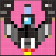
Fig. 15 – A sprite
The transparency (the large magenta-coloured area) is set to index 227 (as we've seen in Chapter 15), the Global Transparency Colour – which for the purposes of our example has been left the default. The rest displays a little spaceship in brown and grey while the cockpit is demonstrated in blue and white.
Let's start with the DATA statements. Some line numbers are omitted as we'll be adding them in the course of our animation example
 10 ; Sprite: Romylos Dokos © 2019
 30 RESTORE
 40 BANK NEW a
 50 FOR F=0 TO 255
 60 READ n: BANK a POKE f,n
 70 NEXT f
 80 SAVE "spaceship.spr" BANK a,0,256
210 REM Sprite Pattern 0
220 DATA 68, 68, 68, 68, 227, 227,
    227, 227, 227, 227, 227, 227, 68,
    68, 68, 68
230 DATA 68, 182, 219, 68, 227, 227,
    227, 68, 68, 227, 227, 227, 68,
    219, 182, 68
240 DATA 68, 68, 68, 68, 227, 227,
    227, 55, 55, 227, 227, 227, 68,
    68, 68, 68
250  DATA 182, 182, 68, 227, 227,
    227, 227, 55, 55, 227, 227, 227,
    227, 68, 182, 182
260 DATA 68, 68,  68, 227, 227, 227,
    68, 68, 68, 68, 227, 227, 227,
    68, 68, 68
270 DATA 240, 68, 68, 227, 227, 227,
    68, 255, 127, 68, 227, 227, 227,
    68, 68, 240
280 DATA 227, 68, 68, 0, 227, 227,
    68, 127, 127, 68, 227, 227, 0,
    68, 68, 227
290 DATA 227, 182, 219, 72, 0, 227,
    182, 0, 68, 68, 227, 0, 72, 219,
    182, 227
300 DATA 227, 182, 219, 72, 182, 0,
    0, 0, 68, 182, 227, 182, 72, 219,
    182, 227
310 DATA 227, 182, 219, 72, 182, 68,
    68, 0, 68, 68, 68, 182, 72, 219,
    182, 227
320 DATA 227, 240, 68, 72, 182, 68,
    68, 0, 68, 68, 68, 182, 72, 68,
    240, 227
330 DATA 227, 227, 227, 72, 182, 68,
    255, 182, 182, 255, 68, 182, 72,
    227, 227, 227
340 DATA 227, 227, 227, 227, 68, 68,
    255, 68, 68, 255, 68, 68, 227,
    227, 227, 227
350 DATA 227, 227, 227, 227, 227, 68,
    255, 182, 182, 255, 68, 227, 227,
    227, 227, 227
360 DATA 227, 227, 227, 227, 227,
    227, 236, 224, 236, 224, 227,
    227, 227, 227, 227, 227
370 DATA 227, 227, 227, 227, 227,
    227, 227, 252, 252, 227, 227,
    227, 227, 227, 227, 227
If you use the 64 or 85 column modes (Via the Edit/Options menu) you'll be able to discern the pattern in a similar manner as you did for the UDGs in Chapter 13. Value 227 is obviously the transparency as we discussed above.
Line 40 is a new command for us (which we will examine in length in Chapter 23) but what it does, is to reserve the first free memory bank and assign its identification number to variable a. This way we don't need to remember –or hard code– an arbitrary number as that number could be in use if this is loaded on another machine.
Next, line 60 reads each value in succession and then writes (with BANK POKE) each value in a progressively increasing offset in bank a. Once the READ process is done, we SAVE the stored values in a file for later use. This particular version of SAVE (SAVE … BANK) will be explained in length in chapters 19 and 23.
Putting Sprites on Screen
The sprite (or rather a pattern that can be assigned to a sprite) is now safely stored in bank a. So how do we display it?
For that we need a few commands. SPRITE CLEAR, SPRITE BANK, SPRITE PRINT, SPRITE BORDER and finally SPRITE.
Let's follow them one by one:
SPRITE CLEAR
clears all sprite assignments and starts fresh. It's a good idea to start any program dealing with sprites with that command so let's insert it into our program immediately with:
20 SPRITE CLEAR
We now have let NextBASIC know that we have no sprites assigned with the previous command, but now we need to assign new ones. This is done with:
SPRITE BANK b [,o, p, n]
which lets NextBASIC know in which bank b, are the sprite patterns located. Optionally you can define a number n of sprite patterns beginning with pattern p, located at bank offset o.
In the case above, we already know the bank and we do not need any more identification factors so let's tell NextBASIC where we put the sprites by adding:
90 SPRITE BANK a
All is now left to do, is show our sprite. For this we need two commands. First we need to enable sprites with:
SPRITE PRINT n
where n can be 0 or 1 enables sprites (1) or disables (0) them. This is actually showing the sprites, but freshly initialised sprites contain no image (pattern), nor display information. We need to assign at least one pattern to one sprite "slot" and tell the Sprite System that the particular sprite "slot" is visible for that to happen.
In our example so far (that will soon change), we only have one pattern so that's not particularly difficult. We also need to place the sprite somewhere on the screen AND possibly rotate it. If you go back to our sprite design, you'll see it's a spaceship facing upwards; we may need to make it turn to the left or right. All of the above (and one more thing) can be achieved with a single command:
SPRITE s, x, y , p, f,rf,mx,my
which in one go: sets sprite number s, to pattern number p, then update its position to location x, y with flags f, relative flags rf, x-scaling mx and y-scaling my.
If the sprite id s is negative, this sprite is a relative sprite, and its position is relative to the previous anchor sprite (defined with a positive sprite id). See later for more information on relative sprites. Flags is a bitmask (we've covered bitmasks before in Chapter 6 so that should be easy already) that sets the following:
Bit 0 is the visibility flag. 0 is for invisible and 1 is for visible
Bit 1 is the rotate flag. 0 for standard, 1 for a 90° clockwise rotation
Bit 2 is the Y–mirror flag. 0 is for non-mirrored vertically while 1 is for mirrored
Bit 3 is the X-mirror flag. Again it's 0 for non-mirrored horizontally while 1 is for mirrored
while
Bits 4 through 7 define a 4-bit palette offset (or 0).
The Relative Flags rf is also a bitmask that sets the following:
The relative-flags parameter, rf, is also a bitmask:
Bit 0: type: 0=composite, 1=unified [only valid for anchor sprites]
Bit 1: pattern is relative to the anchor [only valid for relative sprites]
Bit 2: palette offset is relative to the anchor [only valid for relative sprites]
The scaling parameters mx and my are:
0=1x (no scaling)
1=2x
2=4x
3=8x
Any parameters in the SPRITE command can be omitted, and its value will be left unchanged from the last time it was explicitly specified. It's a good idea again to use the BIN function to easily specify the flag parameters in a more convenient way.
We'll explain in a little bit the part about the palette offset but for now, let's add a non-mirrored, non-rotated sprite 0 with the pattern 0 we defined, put it at approximately the centre
of our screen and make it visible. Let's add the appropriate commands now to our program:
100 SPRITE PRINT 1
130 SPRITE 0,152,119,0,1
to make sure that our sprite will stay on screen (as the NextBASIC editor will make it invisible temporarily when invoked), we should add one more line:
150 PAUSE 0
which will ensure the computer is waiting on our keypress before returning to NextBASIC. Now RUN the program.
Presto! Our Spaceship is sitting idle, doing nothing, in the middle of our screen. But wait a second? 152 and 119 don't look anywhere like the middle of the screen. We know our resolution in Layer 0 can be expressed in values between 0 and 255 for x and 0 and 191 for y correct? Well wrong! It's time now to refer back to Chapter 15 and also examine Fig. 13 one more time where we will see that the Sprite System has a resolution of 320 w x 256 h pixels.
This gives us 32 more pixels on every side than our standard resolution Layer 0 and Layer 2 screens. Now placement of the sprite begins with the upper left corner and a sprite is 16 x 16 so in order to be placed at the centre of the screen you divide the horizontal and vertical in half and then subtract a further 8 pixels to center the sprite. Normally the border hides the sprites so setting an x,y set of 0,0 would leave the sprite invisible. There is something we can do about that however and that's use:
SPRITE BORDER n
which sets the sprites to print over the border if n is set to 1 or under it if n is set to 0. Let's try it by adding the command and changing line 140 to show the sprite at that coordinate with:
105 SPRITE BORDER 1
130 SPRITE 0,0,0,0,1
To execute with the latest changes, do not RUN the program again, as this will repeat the process and commit one more bank to the sprite DATA we entered originally. Instead type GO TO 100. You may even want to test this without line 105 to see the difference. One more command related to the above is:
SPRITE DIM x1,y1,x2,y2
which sets the clip window for sprites from (x1,y1) to (x2,y2). Any part of a sprite outside this window is not visible. Note that this has no effect if sprites over the border (SPRITE BORDER 1) is enabled.
Animating Sprites
This chapter however is called Time and Motion and with sprites so far we haven't seen motion at all! Well, let's change that; as we spoke in the introduction a sprite can be animated by moving it about the screen or by changing its bitmap to something different and most of the time, both at the same time. In order however to animate the bitmap of a sprite, a new pattern has to be defined. Let's do that by adding a few lines to our program and modifying some existing ones. First remove lines 140 and 150, then modify these:
 50 FOR F=0 TO 511
 80 SAVE "spaceship.spr" BANK a,0,512
and then add these:
106 FOR %a= 1 TO 50
139 %s=1-s
140 SPRITE 0,152,119,%s,1
145 NEXT %a
150 PAUSE 0:STOP:REM Exit here after
    pausing
380 REM Sprite Pattern 1
390 DATA 68, 68, 68, 68, 227, 227,
    227, 227, 227, 227, 227, 227, 68,
    68, 68, 68
400 DATA 68, 219, 182, 68, 227, 227,
    227, 68, 68, 227, 227, 227, 68,
    182, 219, 68
410 DATA 68, 68, 68, 68, 227, 227,
    227, 55, 55, 227, 227, 227, 68,
    68, 68, 68
420 DATA 182, 182, 68, 227, 227, 227,
    227, 55, 55, 227, 227, 227, 227,
    68, 182, 182
430 DATA 68, 68, 68, 227, 227, 227,
    68, 68, 68, 68, 227, 227, 227,
    68, 68, 68
440 DATA 240, 68, 68, 227, 227, 227,
    68, 255, 127, 68, 227, 227, 227,
    68, 68, 240
450 DATA 227, 68, 68, 0, 227, 227,
    68, 127, 127, 68, 227, 227, 0,
    68, 68, 227
460 DATA 227, 182, 219, 72, 0, 227,
    182, 0, 68, 68, 227, 0, 72, 219,
    182, 227
470 DATA 227, 182, 219, 72, 182, 0,
    0, 0, 68, 182, 227, 182, 72, 219,
    182, 227
480 DATA 227, 182, 219, 72, 182, 68,
    68, 0, 68, 68, 68, 182, 72, 219,
    182, 227
490 DATA 227, 240, 68, 72, 182, 68,
    68, 0, 68, 68, 68, 182, 72, 68,
    240, 227
500 DATA 227, 227, 227, 72, 182, 68,
    255, 182, 182, 255, 68, 182, 72,
    227, 227, 227
510 DATA 227, 227, 227, 227, 68, 68,
    255, 68, 68, 255, 68, 68, 227,
    227, 227, 227
520 DATA 227, 227, 227, 227, 227, 68,
    255, 182, 182, 255, 68, 227, 227,
    227, 227, 227
530 DATA 227, 227, 227, 227, 227,
    227, 236, 224, 236, 224, 227,
    227, 227, 227, 227, 227
540 DATA 227, 227, 227, 227, 227,
    227, 227, 224, 224, 227, 227,
    227, 227, 227, 227, 227
Now, unlike the previous encouragement, RUN the program again. This will reserve a new bank for sprites which isn't normally recommended but it is okay for the purposes of our example. What we have done now is to create two patterns that are similar but differ slightly in the cannons section and the engine section. Lines 136 to 150 will display sprite 0, 50 succesive times, however where things differ is at line 137 which "flips a switch" from pattern 0 to pattern 1 for sprite 0 displayed at line 140. If you cannot see the effect very well, you can insert a:
PAUSE 3
at the end of line 140 which should give you just about enough delay to see the sprite changing at the engine and cannon sections while at the same time demonstrating how important time control is in animation. We did cover the bitmap animation of the sprite itself; let's now see how we can make it move. First however let's try to rotate the sprite in place so we can also see the usage of the flags in action. Add the following lines:
107 %p=0
108 REPEAT
109 IF %p=0 THEN %f=%@0001
110 IF %p=1 THEN %f=%@0011
111 IF %p=2 THEN %f=%@0101
112 IF %p=3 THEN %f=%@1011
141 REPEAT UNTIL %p>3
and make line 140:
140 SPRITE 0,152,119,%s,%f:PAUSE 3:
    %p+=1
Now execute again with GO TO 100 and you will see the sprite rotate in place.
Notes
SPRITES cannot be saved as parts of any screenshot facility with the NMI menu or via SAVE … LAYER because they exists outside of normal memory space.
The process is quite simple; the last bit being the visibility flag:
First the sprite is printed upright, then the rotation flag bit gets turned on to give it a right angle turn, then it gets turned off and the Y mirror flag bit gets turned on to make the sprite point downwards and finally the rotation flag bit together with the X mirror flag bit get turn on to rotate the sprite clockwise 90° and then mirrored horizontally to make the sprite pointing to the left. The process restarts from the sprite pointing upwards when the rotation variable %p gets reset to 0 and the whole thing repeats 50 times, all the while changing between patterns 0 and 1.
Moving Sprites on Screen
Time to move the sprite about the screen; we'll start easy and then introduce you to the real reason (that is obviously humourus) why maths exist! First remove all lines between 106 and 150 and replace with these:
106 FOR %a = 0 TO 255
130 %s=%1-s
140 SPRITE 0,152, %255-a,%s,1
141 PAUSE 3
145 NEXT %a
150 GO TO 106: REM you'll need to
    stop this with BREAK
Execute with GO TO 100 and you'll see our spaceship fire up its engines and cross the screen from top to bottom. Now for something much fancier as promised, move line 106 to 120 and add these lines:
106 PROC initSXSineMov()
560 STOP
570 DEFPROC initXSineMov()
580 FOR f=0 TO 319:%a[ INT {f}]=% INT
    {159* SIN (f/159* PI )}: NEXT f
590 ENDPROC
Finally modify lines 140 and 150 as follows:
140 SPRITE 0,%159+a[a], %255-a, %s,1
150 GO TO 120
before executing again with GO TO 100. The spaceship now will move in a sinusoidal pattern from the bottom to the top of the screen before wrapping around and coming from the bottom. The way we did this, was by precalculating an integer array (See Chapter 12) to hold all possible x values within our visible Sprite System coordinates. To avoid B Integer out of range errors, we made sure the possible values of both the SIN function results and line 140 that positions the spaceship in the x,y axis stay within acceptable range. To switch the initial direction of movement, instead of a + you can start with a - in line 140 as follows:
140 SPRITE 0,%159-a[a],%255-a,%s,1
Note that our integer array %a is using the brackets [ ] variant instead of the parentheses ( ) variant and that's because we have more than a potential 64 values. That means also that integer arrays %a (), %b (), %c (), %d () and %e () have been used up by %a[ ].
It's obvious by this example that very complex animation patterns can be created with relative ease using the Sprite System. Before we move on to scrolling, it's useful to also cover a few more subjects we did not address in the course of our example.
The first thing is the ability to use palettes with the Sprite System. These are indistinguishable from other palettes in the ZX Spectrum Next palette control system2 and they too are also governed by the PALETTE DIM keyword to set them up as 8 or 9 bit. Like the LAYER PALETTE equivalent, the Sprite System has its own keyword combinations: SPRITE PALETTE and SPRITE PALETTE BANK. Their syntax is as follows:
SPRITE PALETTE n[,i,v]
where n is the palette number (0 for first and 1 for second) while the optional i, v are the colour index (0 to 255) and colour value (expressed in 9-bit RRRGGGBBB format regardless of the PALETTE DIM setting).
SPRITE PALETTE n BANK b, o
will operate like it's LAYER counterpart, assigning palette n from offset o in bank b. As with the LAYER version, palettes are 512 bytes long if 9-bit and 256 bytes long if 8-bit (as set with PALETTE DIM).
2 See Chapter 15 for the Layer 2 notable palette exception
One last thing of note is the palette offset flag we discussed earlier. This is there to allow for quick change of colour scheme on a sprite without changing its bitmap. If you recall the discussion about 4-bit sprites, this is similar but the sprites are actually 8-bit ones. They can still be defined in 8 bit index values however these values' 4 top bits will get chopped off and replaced by the optional offset. Since calculating and/or anticipating and properly structuring your palettes for such a use can be a large hassle; it's good practice if you want to use this feature to define your sprite values from 0 to 15 and set the offset to adjacent sets of 16 colours. This way in a potential future version of NextBASIC that supports native 4-bit sprites, you won't have to change pattern definitions at all.
Relative sprites
Sprites can be grouped together to form composite or unified sprites. Each such grouping consists of a single anchor sprite which is the sprite with the lowest id in the grouping, followed by any number of relative sprites, with sprite ids following the anchor sprite in sequence.
When an anchor sprite moves or becomes invisible, all the associated relative sprites also move or become invisible. It is also possible for individual relative sprites to be made invisible or visible. The rule is that a relative sprite is only visible if its own visibility flag is set and the visibility flag of the associated anchor sprite is set.
To define a relative sprite, simply specify its sprite id as a negative number for example specifying:
SPRITE -1,....
defines sprite 1 as relative to the preceding anchor sprite, with id: 0.
Any number of relative sprites can follow an anchor sprite.
The x and y coordinates specified in SPRITE commands for relative sprites are not actual coordinates, but signed integer offsets in the range -128 to +127 from the coordinates of the anchor sprite. This establishes how close the anchor and the relatives are; in other words they don\t have to touch each other; only when we want to create something visibly bigger looking like one single thing on screen!
Additionally, if the pattern relative flag is set for a particular relative sprite, its pattern number is added to the pattern number from the anchor sprite – wrapping round if the sum exceeds 64.
Using this, it is easy to animate an entire composite/unified sprite simply by changing the pattern of the anchor sprite. This is extremely similar to our small animation example before.
In the same vein, if the palette relative flag is set for a particular relative sprite, its palette offset is added to the palette offset from the anchor sprite (wrapping round if the sum exceeds 16).
Composite vs Unified sprites
The type of a grouping of sprites is determined by the type flag of the anchor sprite: composite or unified. The distinction between them is simple:
For composite sprites, the remaining sprite parameters (rotation, x/y mirrors and x/y scaling) are independent for each relative sprite. This allows creation of a composite sprite where individual relative sprites can be rotated etc for animation purposes whereas for unified sprites, the rotation and x/y mirrors of the relative sprites are relative to that of the anchor sprite.
Therefore, when the rotation or x/y mirrors of the anchor are changed, all the relative sprites rotate or reflect about the anchor. The same goes for the x and y scaling of the indi-
vidual relative sprites in the case of unified sprites; it is completely ignored, thus allowing the entire grouping to be scaled just by changing the scaling of the anchor3.
Batching
The standard SPRITE command normally has immediate effects to what is displayed on the screen. However, it is also possible to place NextBASIC into batching mode.
In this mode, SPRITE command has no immediate effect, but the changes specified are remembered. When all the required changes have been made using multiple SPRITE commands, they can all be applied to the screen at once, giving a more synchronised look to your game and fewer screen tears.
To control batching the following commands are available in the order one would use them:
SPRITE STOP
which enables batching mode and turns off the immediate sprite screen updates
SPRITE MOVE
This command sends all outstanding sprite changes to the hardware immediately (ergo displays all the animation effects and movement that was pending while in batching mode).
SPRITE MOVE INT
The same as above but waiting for the 50 Hz / 60 Hz interrupt to occur. This is useful in order to synchronise the sprite movement to the framerate (making for a smoother animation) and finally
SPRITE MOVE INT y
which works in the same way as SPRITE MOVE INT, except that changes are not sent to the hardware until after the TV scanline corresponding to sprite coordinate y. This avoids flicker by making sure that sprite changes do not happen on screen while the display is midway through displaying the current sprite(s). Finally
SPRITE RUN
disables batching mode and turns the immediate screen updates back on. This is also done by the SPRITE CLEAR command we saw earlier but without the destructive effects.
Automatic sprite movement
As we saw above, moving a sprite can be laborious. In order to reduce the amount of work a NextBASIC program needs to do to animate and move sprites, commands are provided to allow some or all of this work to be done automatically whenever a SPRITE MOVE command is issued. Any sprite can have automatic movement or animation applied to it, and the standard SPRITE command can still be used to perform any other changes when they are needed.
The main command used to set up automatic sprite movement is the SPRITE CONTINUE command:
SPRITE CONTINUE s, [x1 [TO x2]] [STEP xs] [RUN|STOP], [y1 [TO y2]] [STEP ys] [RUN|STOP], [p1 [TO p2]],[f], [r], [d]
Although looking somewhat daunting at first, SPRITE CONTINUE is quite easy to master regardless of its numerous options. As apparent by the brackets, each parameter (or sub-clause of a parameter) is optional. If not specified, the previous value will be retained.
Movement in the x-direction is specified with:
3 This scaling also applies to the relative x/y coordinate offsets
x1: minimum value for x-coordinate
x2: maximum value for x-coordinate (or assumed to be equal to x1 if not provided)
xs: signed step in pixels (between -127...+127) for every horizontal move
and
RUN: indicates movement in the x-direction is initially on or
STOP: indicates movement in the x-direction is initially off
The parameters are equivalent for the y-direction and specified with:
y1: minimum value for y-coordinate
y2: maximum value for y-coordinate (or assumed to be equal to y1 if not provided)
ys: signed step in pixels (between -127..+127) for every move
RUN: indicates movement in the y-direction is initially on
STOP: indicates movement in the y-direction is initially off
Pattern animation is specified with:
p1: minimum value for sprite pattern
p2: maximum value for sprite pattern (or p1 if not specified!)
while movement rates are controlled with:
r: rate at which sprite moves/animates (0-255) where...
0=on every SPRITE MOVE command
1=skip 1 SPRITE MOVE command after moving
2=skip 2 SPRITE MOVE commands after moving
etc
d: delay before initial movement (0-255) where:
0=move on the first SPRITE MOVE command
1=skip 1 SPRITE MOVE command before the first move
2=skip 2 SPRITE MOVE commands before the first move
etc
The flags parameter f is an 8-bit mask (which as seen before is best specified with BIN or @):
bits 1:0 define the behaviour when the x,y limits are reached:
- 00 = reflect this direction
- 01 = stop this direction, start other direction
- 10 = stop this direction
- 11 = stop completely and make sprite invisible
bit 2 flips the Y-mirror flag when y limits are reached
bit 3 flips the X-mirror flag when x limits are reached
bit 4 controls the behaviour of pattern change:
- 0 = cycle upwards, wrapping back to lower limit
- 1 = bounce between lower and upper limits
bit 5 if set, sprite is disabled when its pattern reaches limits
bit 6 if set, updates the pattern even when sprite is stationary and finally
bit 7 if set, X-mirror/Y-mirror/rotation flag are set according to the direction of travel (this bit overrides bits 2 & 3)
The initial position, pattern and other details of the sprite are determined by the last standard SPRITE command. If these values are outside the maximum/minimum ranges, then (depending upon the specified step and RUN|STOP status) they will gradually change until they fall within the max/min range.
If automatic movement is specified for an anchor sprite then, the entire composite or unified sprite will be automatically moved.
Automatic movement, can also be specified for individual relative sprites if this is desired (Since the parameter s is always positive for the SPRITE CONTINUE command, but the sprite remains relative if specified as such in the last standard SPRITE command).
This would be done to animate the relative sprites separately, so that one relative sprite might animate whilst the others remain the same (for example). However, it can also be used to automatically move a relative sprite around within a composite/group sprite. The main restriction here is that the movement limits are unsigned, so this works best for relative sprites with positive offsets (add 256 to negative offsets when specifiying them in a movement range).
Automatic movement can be temporarily suspended for particular (or all) sprites if so desired by using:
SPRITE PAUSE s1 [TO s2]
which turns off automatic movement for a single sprite s1 or a range (s1 – s2) of sprites. Said suspension is lifted by using:
SPRITE CONTINUE s1 [TO s2]
which restarts automatic movement for a single or a range of sprites as above.
Sprite functions
In order to return details about sprites, and to make collision detection checks, several functions are provided4. These are:
SPRITE s
which shows if sprite s is visible. Returns 1 (true) if sprite is visible or 0 (false) if not.
SPRITE CONTINUE s
Returns a bitmask describing the automatic movement enabled for sprite s:
bit 0: set if automatic movement is enabled
bit 1: set if currently moving in the Y axis
bit 2: set if currently moving in the X axis
Note that if bit 0 is set but neither bits 1or 2 are set, that means that only the pattern is being animated.
SPRITE AT(s,c)
Returns a coordinate or other movement-related value for the sprite:
| SPRITE AT(s,0) | returns x coordinate |
| SPRITE AT(s,1) | returns y coordinate |
| SPRITE AT(s,2) | returns pattern number |
| SPRITE AT(s,3) | returns x step |
| SPRITE AT(s,4) | returns y step |
| SPRITE AT(s,5) | returns delay before the sprite next moves5 |
One of the most labour-intensive game programming tasks is trying to figure out when two sprites have collided. NextBASIC provides that information with
SPRITE OVER(s1, s2 [TO s3] [,overlapX [,overlapY] ])
which performs a bounding-box collision detection between sprite s1, and a single other sprite s2 or a range of sprites s2...s3.
Two optional acceptable overlaps (in pixels) can be provided in overlapX and overlapY. If overlapX is not present, 0 (no overlap) is used. If overlapY is not present, then the value of overlapX is used. Overlaps should be 0...7 for an unscaled sprite s1, or 0...15 for a 2x scaled sprite etc. Overlaps allow for some flexibility before declaring a collision especially since sprite patterns do not always extend to the boundaries of the sprite bounding box (16 x 16)
4 All these functions are available in the standard expression evaluator and the integer expression evaluator 5: A returned value of 0 means the sprite will move on the next SPRITE MOVE command.
The function returns 0 (false) if there is no collision or the number of the colliding sprite (s2...s3) if there was a collision.
NOTE: If the colliding sprite's id is 0 then 128 is returned.
Any relative sprites following s2 or s3 will also be checked, until the next anchor sprite that is not in the specified range.
Scrolling
The last method of animation is by using the in-built hardware scrolling capabilities of the ZX Spectrum Next. As you will find out in Chapter 22, all layers can be scrolled either in full or within a clipping window (see Chapter 16 – Graphics). NextBASIC provides access to hardware scrolling via the LAYER AT command. Its syntax is as follows:
LAYER AT x,y
which moves the current layer to the offset defined by the coordinates x and y. According to which side we're moving to, the existing graphics on that side get wrapped around the opposite side. Let's demonstrate using one of the images we generated earlier while doing frame-based animation:
10 LAYER 2,1:CLS
20 LOAD "ANIM0.SL2" LAYER: PAUSE
    0: REM Hasta la vista Kev!
30 FOR %x=0 to 255
40 LAYER AT %x,%0
50 NEXT %x
60 LAYER AT 0,0: LAYER 2,0:LAYER 0
Once you RUN the above, you'll see an image racing towards the left side of the screen so fast it may even be unusable for anything other than a simple effect. Running it at 3.5MHz you will see a very smooth movement which shows how efficient hardware scrolling is on the ZX Spectrum Next.
If you want to reverse the effect and make the screen move towards the right you will need to change line 40 to:
40 LAYER AT %255-x,0
If we borrow a bit from the sprite example, we can even introduce a SIN function to make the screen appear like it's bouncing from left to right and top to bottom and vice-versa.
By itself, the LAYER AT keyword doesn't do much other than roll a screen around; with the combination however of layer clipping windows and background updating of the shadow screens (See Chapters 22 and 23 as well as Chapter 16), you can produce a scrolling effect of very large landscapes. If you combine this with specially crafted screens that can repeat themselves at infinitum then you have the basics for every side scrolling game ever made!
The Copper
While not strictly an animation aid, the Copper is a hardware module of the ZX Spectrum Next that can definitely be used for, among other things, animation. The Copper runs in parallel and independently from the main Z80n processor and is dedicated to writing Next Registers (NexREG) at specific points on the display. The name derives from "co-processor" and was first seen in the Amiga computer which had a similar function. The Copper, essentially maintains a list of instructions that consists of only two commands; WAIT and MOVE. This simple control allows updating of Next registers at regular times, synchronised to points when the display is updated on the screen. The Copper system can therefore be used to send audio samples to the ZX Spectrum Next's digital audio hardware,
make fast colour changes to get sky effects, change layer priorities, enable or disable screen modes etc. all that from a simple list of commands.
On older Spectrum models, you would have needed some very clever use of the Interrupt system to do these sort of tricks with some being completely impossible or just too slow to be of any practical use. Even with the ZX Spectrum Next's ability to generate interrupts on each raster line, setting that up (especially in NextBASIC) and then trying to get the timing right for nice clean effects is very complicated (or impossible) and yet simple to accomplish by using the Copper.
We'll jump ahead a bit and introduce a special command; REG (which will be covered in full in Chapter 22). For now take REG n,v to be the same as OUT 9275, n: OUT 9531,v. Let's see our example:
  10 BORDER 0: PAPER 0: INK 7:CLS
  20 REG 98,0: REM make sure Copper is
     stopped
  30 REG 97,0
  40 REM Select the Copper data
     register
  50 FOR x=0 TO 6: REM Increase this
     if you add more data lines.
  60 READ m,l
  70 REG 96,m: REG 96,l: REM write the
     Copper list from DATA statements
  80 NEXT x
  90 REG 97,0: REM low part of address
 100 REG 98,%@11000000: REM high part
     of address and start Copper,
     repeat on VBlank
1000 DATA 128+(45*2),0:
     REM WAIT for line zero horizontal
     45
1010 DATA 64,16,65,BIN 11100000:
     REM WRITE Palette Index 16 (Paper
     and Border), then WRITE RED
1020 DATA 128+(45*2),100:
     REM WAIT for line 100 horizontal
     45
1030 DATA 64,16,65,BIN 00000000:
     REM WRITE Palette Index 16 and
     WRITE contents back to BLACK.
1040 DATA 128+1,128
1050 REM Last line waits for a bit of
     the screen that does not exist
     1*256+128 = 386 (STOP)
You can try changing the BIN statements in lines 1010 and 1030 to use different colours – this is the 8 bit Palette value so RRRGGGBB
Now remember this list is still running in the background but, it is changing ULA palette 0 paper colour. NextZXOS uses palette 1 so you do not see it when editing NextBASIC. Just type CLS and you will see that it comes back until you press a key!
WAIT commands (where the top bit is 1 i.e. bytes >128) will pause processing until a certain point on the display (to a fixed resolution).
MOVE commands (where the top bit is 0 i.e. bytes <128) will take a given value and put it in the numbered register.
You can have up to 1024 commands which can repeat or stop at any point by WAITing for a non existent line I.e. >311 which works at both 50 and 60 Hz. So there is loads of room for creativity and invention.
Only the lower 128 Next registers can be written but, this is not an issue as the registers above 127 are mainly used for the accelerator and the Expansion Bus.
Register 96 (60h) is the data port to write the instructions. They are two bytes long so you need to write them in pairs with the most significant byte first – not the usual Z80 way but, needed for the way the system works.
Register 97 and 98 (61h and 62h) are the controls; the first is the low 8 binary bits of the address to WRITE the instructions, the second contains the bits to control the mode and the top bits of the instruction address. If you change to mode 01b (from another mode like 00b PAUSE/STOP) this also resets where the Copper begins to READ its instructions from back to instruction 0 – in all other cases it will carry on from where it left off last time.
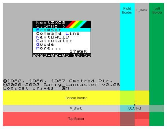
The Copper sees the screen starting from the top left pixel of the display area of the screen, this is 0,0. After 32 horizontal values (every 8 pixels) you have the right border, then you have a gap (count of 12) which is where, on an old TV, the spot would be flying back over to the left, then you have the right hand border of the next horizontal line.
Note: This zero point is also where the screen "dot" will be when the first Raster Line Interrupt occurs. Do not confuse this with normal interrupts on the system which occur in the top left of the whole screen as it is displayed on a monitor or TV. That is actually somewhere in the middle of the bottom right of the Copper view of the screen shown in the diagram below. Exactly at raster line 224 at 60Hz or 248 at 50Hz.
Finally when it gets to the bottom of the screen it has the border and then a blank period (8 lines) while the old spot was running back to the top of the screen, then you have a number of lines in the top of the screen area to play with (56 at 50Hz or 32 at 60Hz). To see this change line 1000 for DATA 128+(45*2),200 and line 1020 for DATA 128+(45*2)+1,45. Remember: 1*256+45 = 301.
This diagram will hopefully help to visualise that:
                                                     Right    H_Blank    Left
                                                     Border              Border

  NextZXOS
  3.5MHz  >
  Browser
  Command Line
  NextBASIC
  Calculator
  Guide
  More...                                1792K
  2023-02-05 10:53


  ©1982, 1986, 1987 Amstrad Plc.
  ©2000-2023 Garry_Lancaster  v2.08
  Logical drives: CM

                                                                Bottom Border


                                                                V_Blank         ULA IRQ

                                                                Top Border
Fig. 16 – Copper operation
If you MOVE 0,0 (i.e. Write something to a Read Only Next Register like Register 0) then the Copper does nothing for a short duration (a NOP in Z80 terms) so you can wait for a more accurate moment to overcome the fact you only have 55 horizontal positions to wait for i.e. every 8 pixels on the screen.
You can write to the Copper as it is running because it keeps a separate track of its READ instruction address to the address you are using to WRITE.
WARNINGS:
Be careful as the NextZXOS Screensaver uses whatever palette is in place so if you have any border effects running they will still be visible and could cause a CRT screen to experience a burn-in effect. This is worth bearing in mind if you are writing software not to leave static images around too long!
If you try to write to a Next Register at the same time as the Copper then this might cause a conflict – don't worry; the Copper will win and the display will be OK but, your program command may fail.
So some care is needed to manage the two systems. Turning off the Copper while you make Next Register affecting changes in NextBASIC is a good idea. That includes things like the PALETTE command for example. If you are using machine code you will need to use some form of flag and remember what the Copper might be doing at a specific time.
In the above program for example, it is possible the Copper STOP in the first two lines will fail if you run it a second or third time to change the colour and will not reset the write address, so you will write after the list already there and your new one will never be reached. You could get around that by repeating the first two lines as it is unlikely to fail twice so shortly after the last attempt and has no effect if it does run twice.
Exercises
-
Write a procedure to write a STOP command twice in a row so that you can make sure the Copper is stopped when you need to in your programs.
-
Draw a Spectrum Flash on the right hand side border by changing the palette colour five times – make sure the last time is back to your real paper/border colour. Hint you can use one or more WRITE 0,0 as a very short delay.
-
Write a program that controls two spaceships using the sprite defined, one going horizontally, while the other vertically on the screen
-
Enhance the above program with a memory based Layer 2 animation running in the background
ZX Spectrum Next User Manual, 3rd Edition (ISBN 978-1-5272-5496-1), written and illustrated by Phoebus R. Dokos. Copyright © 2020-2024 Phoebus Dokos / SpecNext Ltd. Licensed under CC BY-NC-SA 4.0. This is a transcription and can contain errors; check any doubt against the printed page.