Pages 247–270 · Markdown
Chapter 23 – The Memory
Overview
In previous chapters, we talked about binary code, bytes, words and long words. We also discussed strings, floating point and integer numbers. It's time to go into more detail and explore how your computer stores information we put into it.
The kind of data we're processing makes absolutely no difference to the computer. Whether it's music, a game or a document, it ends up as a series of ones and zeros organised as bytes and stored in memory. We can rely on NextBASIC to manage that information or we can do it ourselves as long as we know how!
The ZX Spectrum Next is an 8-bit computer with a 16-bit Address Bus. That means that it stores and manipulates information in 8-bit bytes, and can see at most 65536 of these bytes at one time. Hold onto this information for now as it's important.
ROM and RAM
Memory can be categorized into two kinds: ROM and RAM. ROM (read-only memory) cannot be written to whereas RAM (random access memory) can be both read and written. RAM is where things like the program and display contents are stored because they can change while the computer is running. ROM can be used to hold something permanent like the NextBasic interpreter or NextZXOS. You may have picked up on the discussion of the ROM earlier and may have been wondering how we can load a ROM from a file as described in various places around this book, when ROM is supposed to be permanent and read-only (see for example Chapter 1).
The truth of the matter is that, although the ZX Spectrum Next contains a physical ROM chip, this has nothing to do with the ZX Spectrum Next's operation. The physical ROM is used to configure the Xilinx FPGA and a small amount is used to store a program that configures the machine on boot. The ZX Spectrum Next itself only sees RAM memory supplied by up to four 512K SRAM chips. The unexpanded model has two chips present for a total of 1024K of memory and the expanded model has four for a total of 2048K memory (See Chapter 22 on how to upgrade the RAM to the maximum possible). The ROM contents are loaded into a portion of this RAM and then the hardware is instructed to make that portion read-only. So after the machine boots, those areas of RAM behave just like ROM because running programs cannot change anything stored there. This reproduces the behaviour of the original Spectrums which did use physical ROMs to store the basic interpreter. In other words, for the purposes of NextBASIC and NextZXOS the ZX Spectrum Next indeed has ROM.
The Memory Map
In the introduction of this chapter we talked about how the ZX Spectrum Next has a 16-bit Address Bus and how this fact means the computer can see 65536 bytes (64 Kilobytes) of memory, a figure that includes both ROM and RAM. That is enough to generate the obvious question: But my computer has 16 (or 32) times as much memory, what's the point of having it? And you would be absolutely right to ask this!
The answer to that question is that the computer uses a memory access technique known as bank switching. In this technique there's a distinction between the maximum addressable memory (the amount of memory that the CPU can see, ie 64K in our case) and the amount of physical memory in the system. In the ZX Spectrum Next's case, the physical memory is divided into equally sized portions called banks and the 64K of memory that the computer can see is also divided into the same sized portions called slots. A virtual map of sorts is constructed that tells the hardware what physical memory bank appears in each of the 64K's slots. We shall refer to this virtual map as the memory map. Whenever information located in physical memory is required, the specific physical bank that holds it is entered into the memory map in one of its slots so that the CPU can see the bank in the slot's address range. Paging in the new bank replaces whatever was there before be-
cause the CPU is given a new window in to a different bank in physical memory. This way the usable physical memory can far exceed the memory the CPU can normally see while, at the same time, older software is completely unaware and will continue to run properly without performing any bank switching.
Memory Management
There are two banking schemes employed in the ZX Spectrum Next: Standard and MMU-based banking. The Standard scheme is inherited from the +3 and the other 128K Spectrum models. The MMU scheme co-exists with the Standard scheme but it is unique to the ZX Spectrum Next.
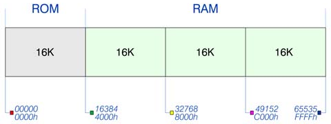
 ROM                              RAM
+----------------+----------------+----------------+----------------+
|      16K       |      16K       |      16K       |      16K       |
+----------------+----------------+----------------+----------------+
 00000            16384            32768            49152            65535
 0000h            4000h            8000h            C000h            FFFFh
Fig. 46 – Standard (NextBASIC) memory map
As you can see, in the memory map NextBASIC uses, the available 64K of addressable memory is divided into four slots of 16K each with the bottom slot always occupied by ROM. Standard banking, inherited from prior Spectrum models, selects which 16K ROM is visible in the bottom 16K slot (addresses 0 to 16383) and which 16K RAM bank is visible in the top 16K slot (addresses 49152 to 65535).
The Spectrum +3 introduced a new, so called, allRAM mode that could place a limited selection of arrangements of four 16K RAM banks into all four slots. This was not widely used and is often forgotten by programmers who mostly target the 128K Spectrum models prior to the +3. A good example of allRAM mode is running CP/M, that requires RAM at the bottom of the address map.
There is a total of four 16K ROMs to select from (inherited from the +3) and a total of 48 16K RAM banks available (112 in 2048K ZX Spectrum Nexts). If you make a quick calculation, that accounts for 832K in the unexpanded Issue 2 ZX Spectrum Next. The remaining portion of the 1024K is allocated to other uses, most notably to divMMC memory. The NextZXOS Startup menu reports available RAM only, which will be either 768K or 1792K.
The Standard banking scheme is controlled by hardware I/O ports (covered in the previous chapter) and via the BANK command and its variants which we will examine soon.
The MMU (memory management unit) scheme is diagrammed below. It is much more flexible in that it can map any 8K bank of physical RAM into any 8K slot of the CPU's addressable memory.
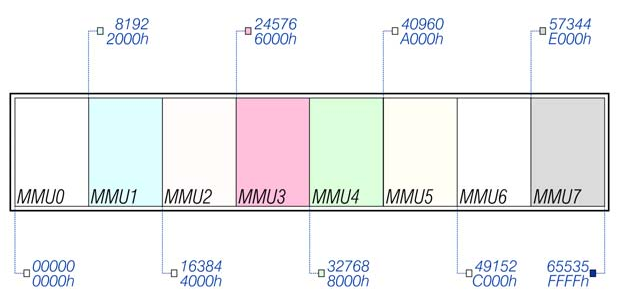
      8192             24576            40960            57344
      2000h            6000h            A000h            E000h
+--------+--------+--------+--------+--------+--------+--------+--------+
|  MMU0  |  MMU1  |  MMU2  |  MMU3  |  MMU4  |  MMU5  |  MMU6  |  MMU7  |
+--------+--------+--------+--------+--------+--------+--------+--------+
 00000            16384            32768            49152            65535
 0000h            4000h            8000h            C000h            FFFFh
Fig. 47 – MMU based memory map
The memory map, is divided into eight slots of 8K named MMU0 through MMU7 and the physical memory is broken into 96 8K banks1. Placing a specific 8K bank n into the address range 0 to 8191, we might say that 8K bank n has been written to MMU0.
Since NextBASIC exposes physical memory banks using the Standard scheme's 16K size, we'll concentrate only on this. More information on using the ZX Spectrum Next's MMU system can be found at the end of this chapter, in other sources such as the Spectrum Next Wiki at wiki.specnext.dev and in Volume 2 – Advanced ZX Spectrum Next programming of this manual.
Reading and Writing to Memory
In the normal course of operations, NextZXOS and NextBASIC read and write memory on your behalf. As it has been demonstrated in previous chapters, we sometimes need to examine the memory's contents or directly modify it. For these cases NextBASIC provides a series of commands and functions to examine and modify memory both in the memory map as well as in the whole of the physical memory. These are all variations of two main keywords, namely the PEEK (and PEEK$) functions (to read the contents of memory) and the POKE command (to alter the contents of memory). The full list follows:
| Command | Description |
|---|---|
PEEK addr |
Reads the byte at address addr |
POKE addr,v |
Changes the contents of address addr to the byte value v |
DPEEK addr |
Reads the word stored at addresses starting at addr (addr, addr+1) |
DPOKE addr, v |
Changes the contents of addresses starting at addr (addr, addr+1) to contain the 16 bit value v |
PEEK$ (addr, len/t) |
Reads memory region of length len stored in the addresses beginning with addr and stores it in a string –or– Reads the string terminated with a user specified terminator t beginning with address addr |
POKE addr, s |
Writes a string s in the addresses beginning with addr |
BANK n PEEK o |
Reads the byte at offset o in bank n |
BANK n POKE o, v |
Changes the contents in bank n at offset o to value v |
BANK n DPEEK o |
Reads the word stored in bank n at offset o (o, o+1) |
BANK n DPOKE o, v |
Changes the contents of bank n starting at offset o (o, o+1) to contain the 16 bit value v |
BANK n PEEK$ (o,len/t) |
Reads a region of length len stored in bank n beginning at offset o and stores it in a string –or– Reads the string terminated with a user specified terminator t from bank n beginning at offset o |
BANK n POKE o, s |
Writes a string s in bank n beginning at offset o |
Table 22 – PEEK and POKE variants
As you can see from the table above, NextBASIC provides us with a wealth of options to manipulate the contents of both the 64K memory map and the physical memory as a whole. These, complemented by the extended options provided by the BANK command, which we will examine further below, can cover almost any memory manipulation need that may arise in the course of writing a program.
Before we continue further with examination of PEEK, PEEK$ and POKE, let's first begin with a warning of sorts: Usage of the non BANK variants is extremely discouraged. Instead it's best, if you use their BANK variants at all times. The reason for that is two-fold and goes back to Memory Banking.
Let's explain; as we said earlier NextZXOS and NextBASIC update portions of the memory map like the system variables or the display memory if need be. What this means, is that you can't really be sure a value you POKEd into the memory map will be there when you try to recover it with PEEK unless you take some measures first2.
Furthermore, POKEing into the memory map unless you absolutely know what you're doing, can have unintended consequences which could result in crashing the machine.
1 224 in a fully expanded ZX Spectrum Next 2: Refer to the CLEAR statement further down this chapter
We'll first give an example of what could go wrong (it's fortunately safe as an example) and then we'll take a detour and explain how the memory map itself is organised from a NextBASIC perspective before returning to PEEK, POKE and their variants. Type:
10 POKE 16384,"ABCabc"
20 CLS:a$=PEEK$ (16384,6)
40 PRINT a$
From what we've talked about thus far, the intention of the program is obvious (for now also never mind what line 10 does; we'll discuss it later). First we put the word ABCabc into address 16384 of the memory map. Then we try to extract it from the same memory location. RUN the program. What do you see? Certainly not ABCabc you were expecting. Now modify lines 20 and 30 and replace 16384 with 20000 in both lines and RUN the program again.
This is perhaps a contrived example but it shows what happens when you try to use memory that is also being used by something else. In this case, address 16384 is where the contents of the display is stored. After placing the string with POKE in address 16384, a CLS is executed which clears the display and the stored string at the same time.
Here is a trickier example:
10 LAYER 1,2
20 POKE 16384,255
30 POKE 24576,255
40 PRINT AT 1,0;"16384 = ";
   PEEK 16384
50 PRINT "24576 = "; PEEK
   24576
This program selects Layer 1,2 (HiRes) and then creates two solid and adjacent character sized lines into the display via the POKE commands in lines 20 and 30. Running the program, the results almost seem correct except the character sized line is only one character wide.
The POKE to 24576 did not go to the display in bank 5 because NextBASIC placed a different memory page in the memory map to cover the last half of bank 5.
Contrast with the following program that does all its PEEKs and POKEs to bank 5 (the BANK commands will be explained in more detail later). As we will see, PEEK and POKE into a 16K bank, is done using an offset into said bank. This means that the "address" range is 0 through 16383; Banks are only 16K long after all. Bank 5, which holds the display is normally placed at address 16384 in the memory map. Performing therefore a POKE into address 16384 is the same as POKE to offset 0 in bank 5. Likewise address 24576 corresponds to offset 8192 in bank 5.
10 LAYER 1,2
20 BANK 5 POKE 0,255:
30 BANK 5 POKE 8192,255
40 PRINT AT 1,0;"16384 = ";%
   BANK 5 PEEK 0
50 PRINT "24576 = ";% BANK 5
   PEEK 8192
This time, the POKE to 24756 (offset 8192) does go to bank 5 and you will see the solid line twice as wide as the first program.
NextZXOS and NextBASIC memory allocation
Before we begin to elaborate on NextZXOS' memory usage, it should be mentioned that Standard memory management and MMU management are internally synchronised for most cases. Every time a 16K bank is being paged in, the equivalent MMU unit gets the 8K bank component of the larger 16K bank NextZXOS uses. As mentioned previously NextZXOS also supports allRAM mode where the ROM is paged out; this is mainly used by CP/M. With this information out of the way, let's see how NextZXOS uses the memory.
By default the first 9 RAM banks are used as follows:
| Bank | Description | Address Range |
|---|---|---|
| 0 | Standard 48K Spectrum memory | 49152 – 65535 |
| 1 | RAMdisk | |
| 2 | Standard 48K Spectrum memory | 32768 – 49151 |
| 3 | RAMdisk | |
| 4 | RAMdisk | |
| 5 | Standard 48K Spectrum memory | 16384 – 32767 |
| 6 | RAMdisk | |
| 7 | Used for workspace and data structures by NextZXOS | |
| 8 | Used for additional screen data (for LoRes, HiRes and HiColour) and other data by NextZXOS | |
| 9 – 111 | Available for user programs (By default banks 9,10 and 11 are used by Layer 2) |
Generally speaking, banks 9+ are always available to the programmer, and can be accessed using the BANK command, while banks 0 – 8 can be used with the following exceptions:
- Bank 0 can be used, only if CLEAR has set the RAMTOP to below 49152.
- Bank 2 can be used, only if CLEAR has set the RAMTOP to below 32768.
- Banks 1,3,4,6 can be used if the BANK 1346 USR command has been used.
- Banks 7 and 8 can never be used.
- Bank 5 can be used with caution.
- Banks 9, 10 and 11 can be used for other purposes if you aren't using Layer 2 or you have changed their assignments with the LAYER BANK command.
From the above, it is easy to surmise what the initial bank assignments are after boot:
| Slot 1 | Slot 2 | Slot 3 | Slot 4 |
|---|---|---|---|
| ROM | Bank 5 | Bank 2 | Bank 0 |
In case you were thinking that this looks easy enough – I could page in any bank I want, don't! In actuality, NextZXOS and NextBASIC expect certain things to be in certain places at all times within the memory map which is organised in the following manner:
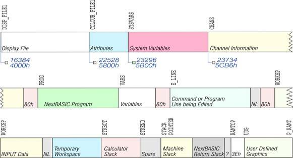
 DISP_FILE1                    COLOUR_FILE1           SYSVARS            CHANS
+------------------------------+----------------------+------------------+---------------------~
| Display File                 | Attributes           | System Variables | Channel Information ~
+------------------------------+----------------------+------------------+---------------------~
  16384/4000h                    22528/5800h            23296/5B00h        23734/5CB6h

    PROG                                  VARS       E_LINE                       WORKSP
+-~~+----+------------------------+---------+---+-----------------------+--+---+~~-+
| ~ |80h | NextBASIC Program      |Variables|80h| Command or Program    |NL|80h| ~ |
| ~ |    |                        |         |   | Line being Edited     |  |   | ~ |
+-~~+----+------------------------+---------+---+-----------------------+--+---+~~-+

 WORKSP                    STKBOT           STKEND  STACK                RAMTOP   UDG    P_RAMT
                                                     POINTER
+-------+--+---------------+---------------+-------+--------+-------------+--+----+--------------~
|INPUT  |NL| Temporary     | Calculator    | Spare | Machine| NextBASIC   |? |3Eh | User Defined ~
|Data   |  | Workspace     | Stack         |       | Stack  | Return Stack|  |    | Graphics     ~
+-------+--+---------------+---------------+-------+--------+-------------+--+----+--------------~
Fig. 48 – Memory map usage by NextBASIC
As seen in the figure above, the memory map is divided into different areas that store different kinds of information. The areas are only large enough for the information that they actually contain, and if you insert some more at a given point (for instance by adding a program line or variable) space is made by shifting up everything above that point. Conversely, if you delete information then everything is shifted down. Some areas as you can see include an address below and a name above them whereas others only a name. The areas beginning at an address, signify fixed points in memory such as the Display and Colour Files, the System Variables and the Channel Information. The first three fixed points are required while the fourth (Channel information) is an unintended consequence! Let's see why:
The Display and Colour Files are as we've seen in previous chapters, legacy areas. The display hardware expects them at these addresses and cannot move inside the memory map. They contain the standard Layer 0 display memory and parts of Layer 1 with the rest appearing as needed and managed by NextZXOS.
The System Variables on the other hand are the system's directory; they contain most information regarding both NextZXOS and NextBASIC and provide information on the boundaries between the rest of the memory areas on the memory map. In other words following the discussion above, if, say, the last program line changes, it's stored within the area pointed to by the system variable PROG. Some of these locations are marked by the names above the areas in the diagram. A complete list follows in the next chapter. Note, that these are NextZXOS variables and not NextBASIC variables, so typing these names means nothing to NextBASIC.
Now you probably noticed that we said most information regarding NextZXOS and NextBASIC and not all information. That's because the information that's held in System Variables (or SYSVARS) deals with legacy applications and compatibility. NextZXOS maintains even more unmovable information elsewhere, tucked away in protected banks and manages it there.
Memory Areas and their use
Below, let's examine some of the memory areas portrayed in the figure above, as it's helpful to generally know how things are laid out in the memory map.
The Display and Colour Files areas store the bitmap for the Layer 0 (and part of the Layer 1) picture. As we saw in chapters 14 through 16, it is rather curiously laid out, so you probably won't want to PEEK or POKE in it. The upshot of all this is that if you're used to a computer that uses PEEK and POKE on the screen, you'll have to start using SCREEN$ and PRINT AT instead, or PLOT and POINT.
The System Variables area, contains various pieces of information that tell the computer what sort of state the computer is in. They are listed fully in the next chapter, but for the moment note that there are some (called CHANS, PROG, VARS, E_LINE and so on) that contain the addresses of the boundaries between the various areas in memory. These are not NextBASIC variables, and their names will not be recognised by the computer.
The Channel Information area contains information about the input and output devices as seen in Chapter 20.
The NextBASIC Program and Variables areas contain your program and its variables, organised in standard data structures we will examine in the following section.
The calculator is the part of the NextBASIC system that deals with arithmetic, and the numbers on which it is operating are held mostly in the Calculator Stack area.
The Spare area contains the space so far unused.
The Machine Stack area is space reserved for the CPU stack.
Similarly, the NextBASIC return stack area which was mentioned in Chapter 4 maintains a record of your program's currently-active subroutine and procedure calls, loops and error handlers.
The byte pointed by the RAMTOP variable shows the maximum address that is reserved for use by a NextBASIC program. We will visit this in more detail, in the section about the CLEAR command below.
Finally the User Defined Graphics area holds all the definitions to the system's UDGs as discussed in Chapter 13.
NextBASIC Data Structures
NextBASIC stores numbers, strings, arrays, programming lines and FOR...NEXT loops in strictly defined forms called data structures. The following discuss all these data structures that are user accessible. Integer-based variables, arrays and control structures are not available to the user and are hidden by NextZXOS in protected memory areas so they're not covered here.
Each line of NextBASIC program has the form:

 MSB  LSB
+---------+---------+-----------~ ~-----------+-----------------+
| 2 bytes | 2 bytes |           ~ ~           | 0 0 0 0 1 1 0 1 |
+---------+---------+-----------~ ~-----------+-----------------+
  Line     Text                Text                  ENTER
  number   Length
             +
           ENTER
Note that, in contrast with all other cases of two-byte numbers in the Z80N, the line number here is stored with its more significant byte (MSB) first: that is to say, in the order that you write them down (also known as Big-Endian order).
A numerical constant in the program appears as ASCII text followed by its binary form, using the character CHR$ 14 followed by five bytes for the number itself.
The variables have different formats according to their features. The letters in the names should be thought as starting off in lower case. The available variants and their formats are:
Number whose name is one letter only:

+-----------------+----------+----+---------~ ~---------+
| 0 1 1           | Exponent |Sign| 4 mantis~ ~sa bytes |
|                 | byte     |Bit |         ~ ~         |
+-----------------+----------+----+---------~ ~---------+
        [?]                         [?]
Number whose name is longer than one letter:

+-----------------+-----------------~ ~-----------------+----------+----+---------~ ~---------+
| 1 0 1           | 0               ~ ~ 1               | Exponent |Sign| 4 mantis~ ~sa bytes |
|                 |                 ~ ~                 | byte     |Bit |         ~ ~         |
+-----------------+-----------------~ ~-----------------+----------+----+---------~ ~---------+
  Letter (≥60h)       2nd Letter           Last Letter                    Value
Array of numbers:
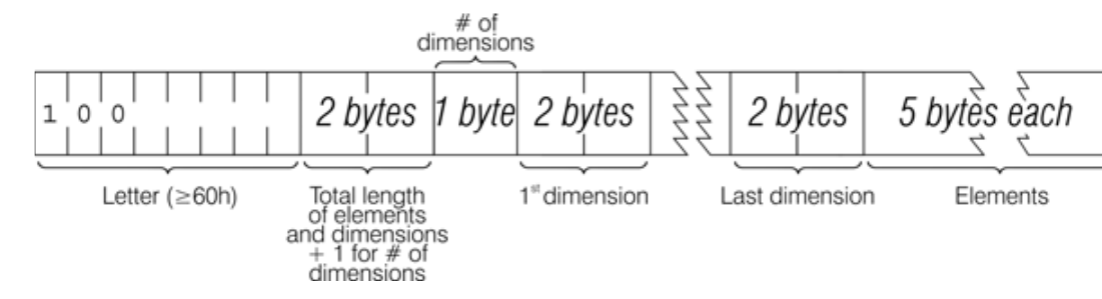
                                    # of
                                 dimensions
+-----------------+-------------+--------+---------~ ~---------+-------------~ ~-------------+
| 1 0 0           | 2 bytes     | 1 byte | 2 bytes ~ ~ 2 bytes | 5 bytes each~ ~             |
+-----------------+-------------+--------+---------~ ~---------+-------------~ ~-------------+
  Letter (≥60h)    Total length           1st dimension  Last dimension     Elements
                   of elements
                   and dimensions
                   + 1 for # of
                   dimensions
Array of numbers whose name is longer than one letter:

                                                                                     # of
                                                                                  dimensions
+-----------------+-----------------+-------------~ ~-----------------+---------+--------+---------~ ~---------+-------------~ ~-------------+
| 0 1 1 1 1 1 1 1 | 1 0 0           | 0 1 1       ~ ~ 1               | 2 bytes | 1 byte | 2 bytes ~ ~ 2 bytes | 5 bytes each~ ~             |
+-----------------+-----------------+-------------~ ~-----------------+---------+--------+---------~ ~---------+-------------~ ~-------------+
       7Fh          Letter (≥60h)     2nd Letter      Last Letter (≤80h)                 1st dimension  Last dimension     Elements
Specifically for arrays the order of the elements is as follows:
- first, the elements for which the first subscript is 1;
- next, the elements for which the first subscript is 2;
- next, the elements for which the first subscript is 3;
and so on for all possible values of the first subscript.
The elements with a given first subscript are ordered in the same way using the second subscript, and so on down to the last. As an example, the elements of the 3 x 6 array b in Chapter 11 are stored in the order b(1,1) b(1,2) b(1,3) b(1,4) b(1,5) b(1,6) b(2,1) b(2,2) ... b(2,6) b(3,1) b(3,2) ... b(3,6).
Control variable of a FOR...NEXT loop:

                                                                    Statement
                                                                     # within
                                                        LSB   MSB      line
+-----------------+---------+---------+---------+-------------+--------+
| 1 1 1           | 5 bytes | 5 bytes | 5 bytes |   2 bytes   | 1 byte |
+-----------------+---------+---------+---------+-------------+--------+
  Letter (≥60h)      Value     Limit     Step    Looping line
Control variable of a FOR...NEXT loop whose name is longer than one letter:

                                                                                                        Statement
                                                                                                         # within
                                                                                            LSB   MSB      line
+-----------------+-------------~ ~-----------------+---------+---------+---------+-------------+--------+
| 1 0 1           | 0 1 1       ~ ~ 1               | 5 bytes | 5 bytes | 5 bytes |   2 bytes   | 1 byte |
+-----------------+-------------~ ~-----------------+---------+---------+---------+-------------+--------+
  Letter (≥60h)     2nd Letter    Last Letter (≤80h ≥20h)  Value     Limit     Step    Looping line
String:

+-----------------+-------------+--------------~ ~--------------+
| 0 1 0           | 2 bytes     |              ~ ~              |
+-----------------+-------------+--------------~ ~--------------+
  Letter (≥60h)     Number of       Text of string (may be empty)
                    characters
String whose name is longer than one letter:

+-----------------+-----------------+-------------~ ~-----------------+---------+--------------~ ~--------------+
| 0 1 1 1 1 1 1 1 | 0 1 0           | 0 1 1       ~ ~ 1               | 2 bytes |              ~ ~              |
+-----------------+-----------------+-------------~ ~-----------------+---------+--------------~ ~--------------+
       7Fh          Letter (≥60h)     2nd Letter      Last Letter (≤80h)            Text of string (may be empty)
Array of characters:
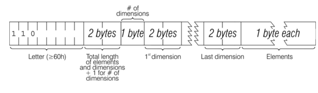
                                    # of
                                 dimensions
+-----------------+-------------+--------+---------~ ~---------+-------------~ ~-------------+
| 1 1 0           | 2 bytes     | 1 byte | 2 bytes ~ ~ 2 bytes | 1 byte each ~ ~             |
+-----------------+-------------+--------+---------~ ~---------+-------------~ ~-------------+
  Letter (≥60h)    Total length           1st dimension  Last dimension     Elements
                   of elements
                   and dimensions
                   + 1 for # of
                   dimensions
Array of characters whose name is longer than one letter:

                                                                                     # of
                                                                                  dimensions
+-----------------+-----------------+-------------~ ~-----------------+---------+--------+---------~ ~---------+-------------~ ~-------------+
| 0 1 1 1 1 1 1 1 | 1 1 0           | 0 1 1       ~ ~ 1               | 2 bytes | 1 byte | 2 bytes ~ ~ 2 bytes | 1 byte each ~ ~             |
+-----------------+-----------------+-------------~ ~-----------------+---------+--------+---------~ ~---------+-------------~ ~-------------+
       7Fh          Letter (≥60h)     2nd Letter      Last Letter (≤80h) Total length       1st dimension  Last dimension     Elements
                                                                        of elements
                                                                        and dimensions
                                                                        + 1 for # of
                                                                        dimensions
As you saw in the examples above, numerical values are represented as 5 bytes. These are floating-point values. In contrast to integers which are – as discussed in Chapter 6 and referenced in Chapters 8 through 11 – of a fixed 16 bit (or two-byte) size, floating-point numbers can represent both decimal and integer values. Due to the calculations involved, their usage will slow down your programs; so avoid using them if you do not need decimal points or values higher than 65535.
For floating-point values, any number (except 0) can be written uniquely as: ± m x 2e
where ± is the sign, m is the mantissa, which lies between ½ and 1 (it cannot be 1), and e is a biased exponent.
Suppose you write the fractional m in binary. Because it is a fraction, it will have a binary point (like the decimal point in decimal) and then a binary fraction (like a decimal fraction). So in binary:
| one half | is written as | .1 |
| one quarter | is written as | .01 |
| three quarters | is written as | .11 |
| one tenth | is written as | .000110011001100110011 |
and so on.
With our number m, because it is less than 1, there are no bits before the binary point, and because it is at least ½, the bit immediately after the binary point is a 1. To store the number in the computer, we use five bytes, as follows:
I. write the first eight bits of the mantissa in the second byte (we know that the first bit is 1), the second eight bits in the third byte, the third eight bits in the fourth byte and the fourth eight bits in the fifth byte II. replace the first bit in the second byte which we know is 1 by the sign: 0 for plus, 1 for minus III. write the exponent +128 in the first byte.
For instance, suppose our number is ¹/₁₀:
¹/₁₀ =⁴/₅ x 2⁻³
Thus the mantissa m is .11001100110011001100110011001100 in binary (since the 33rd bit is 1, we shall round the 32nd up from 0 to 1), and the exponent e is -3.
Applying our three rules gives the five bytes: [?]
There is an alternate way of storing whole numbers between -65535 and +65535:
I. the first byte is 0 II. the second byte is 0 for a positive number, FFh for a negative one III. the third and fourth bytes are the less and more significant bytes of the number (or the number +131072 if it is negative), IV. the fifth byte is 0.
This is essentially the two's complement representation we discussed in Chapter 6 for integers with two extra bytes, one before and one after the number and an entire byte dedicated to the sign as opposed to one bit only. Compared to the integer type supplied by the Integer Expressions evaluator, it is wasteful memory-wise and slower to process.
PEEK, POKE and their variants
Now that we've examined more thoroughly what the memory map looks like to NextBASIC, it's time to revisit the commands and functions that read and modify its contents.
To inspect the contents of one or more memory locations, we use the PEEK, DPEEK and PEEK$() functions; The PEEK variant functions are always safe to use as they change nothing in memory; they can however give unpredictable results in cases where a memory location is marked for moving. As we saw however, there are places in memory which are unmovable; reading in the System Variables area for example is a always a predictable scenario. For instance, this program prints out the first 21 bytes in ROM (and their addresses):
10 PRINT "Address"; TAB 8; "Byte"
20 FOR a=0 TO 20
30 PRINT a; TAB 8; PEEK a
40 NEXT a
All these bytes will probably be quite meaningless to you, but the processor understands them to be instructions telling it what to do.
DPEEK is similar but since it returns 16 bit values, the example above would have to be rewritten as follows:
10 PRINT "Address"; TAB 8; "Word"
20 FOR %a=0 TO 20 STEP 2
30 PRINT %a; TAB 8; DPEEK %a
40 NEXT %a
Generally speaking, (D)PEEKing into ROM is very much useless and it's much more likely that you'll use (D)PEEK to either read a system variable or read a value you've previously POKEd. (D)PEEK$ () on the other hand returns the values at an address in memory in the form of a string. Its syntax is as follows:
PEEK$ (address, argument)
where address is any address in the memory map, while argument can be one of the following:
- A number signifying a length of characters to be retrieved
- A single tilde ~ character, to find any bit-7 terminated string (that means that bit-7 of the last character in the string is set)
- A tilde ~ character followed by the ASCII code of one character that terminates the string
Let's look at an example which helps us search in memory (albeit very slowly):
10 RUN AT 3: REM this takes a
   long time!
20 FOR %a=0 TO 65535
30 PRINT AT 0,0;"Now scanning
   address:";%a
40 a$= PEEK$ (%a,8)
 50 IF a$="Variable" THEN PRINT
    AT 1,0;"Found word at
    address:";%a: GO TO 70: REM
    stop iterating here and go
    below
 60 NEXT %a
 70 FOR %a=0 TO 65535
 80 PRINT AT 3,0: "Now scanning
    address:";%a
 90 a$ = PEEK$ (%a, ~101)
100 IF a$="Variabl" THEN PRINT AT
    4,0; "Found word at address ";%a
110 NEXT %a
You'll undoubtedly notice that line 100 says Variabl instead of Variable and that's because the terminator character we set in like 90 to look for, is not included in the string returned by PEEK$(). What this program actually finds is the address in the memory map where line 50 is stored! The second half of this example (lines 70 on) is very much pointless but was made to show the flexibility of PEEK$()'s arbitrary termination character search.
Normally, it is much more likely to read for NUL terminated strings (~0), FFh terminated strings (~255), often used in +3DOS/IDEDOS and perhaps CR terminated strings (~13), if for example the data you're searching for has been PRINTed with line separators.
To change the contents of a RAM address in the memory map, we use the POKE or DPOKE statements. These have the form:
POKE address, value1[,value2[,value3...[,valueN]]]
DPOKE address, value1[,value2[,value3...[,valueN]]]
The ability to POKE gives you immense power over the computer if you know how to wield it; and immense destructive possibilities if you don't. It is very easy, by poking the wrong value in the wrong address, to lose vast programs that took you hours to type in. Fortunately, you won't do the computer any permanent damage.
As we mentioned earlier, POKE is generally not safe to use within the confines of the memory map, unless you either know what you're doing, or the area you're modifying is fixed (like say the Layer 0 screen or attribute areas or the System Variables – the latter always with caution). It's also safe to POKE within the memory map if you have used the CLEAR command and modify the area above it.
Let's try modifying a system variable to show how powerful POKEing can be:
First, type test in the editor and once you hit ENTER your computer will complain with a buzzing sound. The variable that holds let length of that buzz is called RASP and it's located in address 23608 (5C38h) within the System Variables area.
Now, let's see how can we adjust that buzz. We'll start by looking what is its current value with:
PRINT PEEK 23608
Then modify it with
POKE 23608, 16
Type test again and press ENTER. The buzz indicating the error in your code, shortened in length. You can experiment with different values. The new value you enter must be between -255 and +255, and if it is negative then 256 is added to it.
POKE is not confined into a simple byte sized value as you may have surmised. In fact it can accept a mix of numbers and strings, in a comma separated list of values with each accepting an optional tilde ~ character suffix. In the case of numeric values, the optional tilde suffix after each value makes that value 16 bits wide (a word) while in the case of strings, the optional tilde suffix sets the most significant bit of the last character in the string, usually known as bit7-termination. This is sometimes used in order to store variable-length strings in a compact way. However, it's usually more convenient to use a byte such 0 (NUL) (null-termination), 255 (FFh) or 13 (0Ch) (CR) to terminate a variable-length string in memory. Note that for DPOKE, the tilde is used after numeric values to specify values that should be written to memory as a byte rather than a 16 bit word. You can therefore think of the tilde as a write this value in the opposite way to the default for this command designator! Let's see a few examples:
POKE 32768,200
modifies the contents of the byte address 32768 to 200.
POKE 32768,8,9,10,"test",30000~,55
modifies the contents of address 32768 to 8, address 32769 to 9, address 32770 to 10, addresses 32771 to 32774 to contain the string test (or in other words the values 116, 101 ,115 and 116 respectively – the ASCII codes for the letters making up the word test), addresses 32775 and 32776 to contain values 48, 117 respectively (or 117 x 256 + 48 = 30000) and finally address 32777 to 55. In other words we POKEd 3 bytes, a string, a word and a byte.
DPOKE 32768,1000,2000,3000,100~,2
modifies addresses 32768 though 32775 (pokes 3 words, a byte **–with the tilde–**and a word).
In Chapter 13 we briefly discussed POKE USR "letter". That may look like a separate variant of POKE but in reality USR "letter" is just as shortcut to the address of the UDG defined by letter. There is a small caveat that when used in a single value context, 8 successive POKE USR commands must be given (one for each row in the 8x8 matrix of the UDG) so it's always better if we use it in a list of values context, like so:
POKE USR "A",1,3,7,15,31,63,127,255
which redefines UDG A.
Using POKE with strings is equally powerful so it deserves a separate example. Let's use the example that used PEEK$() to search for a string in order to demonstrate a bit of NextBASIC memory areas magic! First delete all lines after 60 and modify line 20 to read:
20 %a=22000 TO 65535
(This change is to make sure the program doesn't take forever).
RUN the program and when you find the address, note it down, then do the following:
POKE address, "Horrible"
where address is the address you noted earlier. Press ENTER, then write LIST and look at line 50. See? Magic!
Note that using the first form of POKE to any address between 0 and 16383 (the ROM slot) will have no effect regardless of what you attempt to do as shown by this example:
FOR %f=0 TO 16383: POKE %f,0: NEXT %f
The same however is not entirely accurate for DPOKE and the string POKE version of the command. For example both the commands that follow will NOT write in the ROM slot but WILL write in the RAM slot (it so happens as you see from the previous figure) that the first area right after the ROM is DISP_FILE so you'll see a visual result immediately:
POKE 16383, "This is a test":PAUSE 0
and
DPOKE 16383, 65535: PAUSE 0
will both produce a visible result in the upper left corner of the display while the ROM slot is not affected.
CLEAR
When looking at the different memory areas maintained by NextBASIC, we briefly mentioned the System Variable RAMTOP. This variable (located at address 23730) contains the address of the last byte used by NextBASIC. Even NEW, which clears the RAM out, only does so as far as this address – so it doesn't change the user-defined graphics. You can change the address RAMTOP points to by putting it as an numeric argument in a CLEAR statement as follows:
CLEAR new_RAMTOP
This effectively does 4 things:
- clears out all the variables
- clears the display file (like CLS)
- does RESTORE
- clears the NextBASIC return stack and puts it at the new_RAMTOP address – assuming that this lies between the calculator stack and the physical end of RAM; otherwise it leaves RAMTOP as it was.
RUN also performs a CLEAR, although it never changes RAMTOP.
Using CLEAR in this way, you can either move RAMTOP up to make more room for NextBASIC by overwriting the user-defined graphics, or you can move it down to make more RAM that is preserved from NEW. It can also be used to ensure that the machine stack is below BFE0h (49120) when intending to call NextZXOS – this means that the stack will not have to be subsequently moved within your own machine code.
Type NEW, select NextBASIC, then CLEAR 23800 to get some idea of what happens to the machine when it fills up. You'll immediately get an M RAMTOP no good error message. Trying CLEAR 23900 will report 0 OK but attempting to write a program will stop with a buzzing sound very quickly. That means that the NextBASIC user program memory is now full and you will have to make room before typing any more. There are also two error messages with roughly the same meaning, 4 Out of memory and G No room for line.
It's worth mentioning that the Clear option in the NextBASIC menu (accessible by pressing the EDIT key) can also be used to CLEAR memory and it's particularly useful if you have cleared RAMTOP too low and no longer have enough memory to enter NextBASIC commands as with the example above. It sets RAMTOP to just below the current UDG area (ie. equivalent to CLEAR % DPEEK 23675-1, one less than the value in the UDG SysVar).
Memory Bank management with BANK
Under NextBASIC the system's memory capacity is shown in the on-screen menus. It can also be queried programmatically by examining the new system variable, MAXBNK, which contains the number of the highest usable bank in the system (normally 47 or 111)3.
3 The dot command .mem also returns the memory information, although measured in 8K banks.
To make all the extra memory easily accessible to the user, NextBASIC provides a special command called BANK which can be combined with a number of normal commands to extend their functionality to the whole of the ZX Spectrum Next's memory and not just the memory map addresses. We've seen some already used in the course of this guide, especially in chapters 14 through 17 as well as Chapter 20.
Memory banks are marked as in-use or free by the user or by commands that access them (BANK … PEEK / PEEK$ / POKE / COPY / ERASE / USR / LAYER, LAYER … BANK and LOAD … BANK). Users can mark a bank as in-use or as free, by either using an explicit command from the list above or one of the two special commands BANK NEW var and BANK n CLEAR.
BANK NEW var
Reserves the next available free bank number and assigns it to the numeric variable var, ready for use with and by other BANK commands. This command is useful for allocating banks for use in NextBASIC, allowing for cases where a resident machine code program has previously allocated banks for its own use.
Note, that is not essential to use this command, as commands such as LOAD … BANK will automatically allocate the specified bank for use by NextBASIC, but only if the specified bank is not already in use by a resident machine code program.
Let's try a small example. Assuming you have a 2048K ZX Spectrum Next; type the following program:
10 FOR %f = 0 TO 111
20 BANK NEW a
30 PRINT AT 0,0; "Allocating
   bank:"; a
40 NEXT %f
Once you RUN it, the program will begin to allocate memory banks and print the ones it allocates; you'll notice two things: Allocation begins at bank 111 (47 if using an unexpanded KS1/Issue 2 ZX Spectrum Next) and progresses backwards and that program execution will stop abruptly with a 4 Out of memory error report once you reach a bank that's allocated by the system as described in the NextZXOS and NextBASIC Memory Allocation section. Indeed, if you use the dot command .mem then you'll see that you have 0 banks free (0K). In order to free up a bank to be used, you will need to use the BANK n CLEAR command whose syntax is as follows:
BANK n CLEAR
Marks bank n as free for use by other parts of the system (eg dot commands).
Let's try to free a bit of memory after the mess we've made with the previous program. Without making any more changes, let's try:
BANK 11 CLEAR
More likely than not, the system will report: In Use, 0:1. What has happened? Most likely that the bank itself is in use by the system. Let's try again:
BANK 12 CLEAR
This time the system will most likely report: 0 OK, 0:1. We can verify this by running .mem again. This time it will show us 2 Banks free (Remember .mem reports memory in MMU sized banks – that is 8K). Bank 11 you tried to free originally (unless the system hasn't been modified), is being used by Layer 2 (which takes 3 banks, by default 9,10 and 11but can be changed by the LAYER…BANK command) so it's rightfully marked as in-use. Note
here that if you're not using Layer 2, the banks it occupies CAN be used for other purposes including machine code programs. They just cannot be released.
Banks marked as in-use, remain reserved after a NEW command and are only released at a reset (or with this BANK n CLEAR).
BANK CLEAR reports A Invalid Argument, 0:1 if you try to clear banks 1,3,4 and 6 even if you have given the BANK 1346 USR command which is described below.
NextZXOS allocates 64K to the RAMdisk by reserving banks 1,3,4 and 6; BANK 1346 USR allows you to release these for use by your programs. Once you give the command:
BANK 1346 USR
the following things happen; first all files in the RAMdisk are deleted, then the drive itself is unmounted and using BANK commands on these banks stops producing errors. To undo this action and reinstate the RAMdisk you will need to use:
BANK 1346 FORMAT
which will erase the contents of these banks and re-attach them to the RAMdisk. The disk itself however will need to be manually mounted again by using the MOVE...IN command. See Chapter 19 for details.
Bank contents can be copied and erased in whole or in part using the BANK COPY and BANK ERASE commands.There's also a specific one that copies data quickly to and from the screen but we'll look at that separately. The syntax to copy bank data is:
BANK source_bank COPY [source_offset, len] TO destination_bank [,dest_offset]
where source_bank is a readable bank number to copy from while destination_bank is a writeable bank number. Source_offset and len signify the location within the source bank and the size in bytes of the memory chunk we're copying. If the latter are specified, then the dest_offset must also be specified. Let's try:
BANK 9 COPY TO 47
will copy the bank holding the first third of Layer 2 into bank 47 while,
BANK 1 COPY TO 47
will return A Invalid argument, unless BANK 1346 USR has been used!
BANK 9 COPY 8192, 8192 TO 47, 0
will copy the bottom half of the first third of the Layer 2 screen to the start of bank 47 (Once you untangle that tongue-twister you can see how this can create interesting blinds effects!).
It's also quite handy to quickly erase the whole or part of a bank (fill it with zeroes or an arbitrary byte value). This is accomplished by the BANK ERASE command whose syntax is:
BANK n ERASE [offset, len][,][value]
where n is the number of writeable bank, offset is the optional starting point of the erase and len is the length (in bytes) of the area to be erased. The optional value will fill the area with a byte of your choosing or – if omitted – 00h. Here are some examples using Layer 2 and an image present in your System/Next™ distribution (you will need to provide the image in 256 x 192 x 256 colour BMP format):
10 CD "ENTER HERE THE FOLDER"
20 LAYER 2,1
30 .bmpload yourfile.bmp
 40 BANK 9 COPY TO 111: REM
    first we copy it
 50 PAUSE 0: REM wait for a
    key
 60 BANK 9 ERASE 128:; Erase it with
    value 128 which is by default a
    red colour for Layer 2
 70 PAUSE 0:; wait for a key
 90 BANK 111 COPY TO 9:; restore it
100 PAUSE 0:; wait for a key
110 LAYER 2,0: LAYER 0
You can see easily how fast this happens (and how it can be used for a myriad of applications)
Using BANK with graphics
Over the course of chapters dealing with graphics, we've used a lot of graphics-related commands that involved the use of BANK. These are BANK LAYER, LAYER BANK, LAYER PALETTE BANK, SPRITE PALETTE BANK, SPRITE BANK, TILE BANK and TILE DIM all benefiting all providing significant speed enhancements both in development and in usage.
We saw above the use of BANK COPY to copy data from one bank to another. This includes Layer data as they too are kept in banks and managed by NextZXOS. There is however a specially crafted command that does this and more as it adds more options specifically tuned to the requirements of display. Unlike BANK COPY, this is designed to update small areas of the screen to facilitate effects and especially animation. The command is BANK LAYER and it is used to quickly copy data from a memory bank to the screen in the current mode, or vice versa. The syntax is as follows:
BANK n LAYER x,y,w,h|offset TO [raster_op] offset|x,y,w,h
where n is the source OR destination bank number, x and y is the top left character position expressed in character column and row coordinates, w, h are the width and height again in characters of the area to be copied from or copied to, offset is the starting offset in the bank we'll be copying to or from while raster_op, is an optional symbol modifier to TO that affects the data being copied at their destination (does not affect the source data).
TO raster_op can be one of the following values:
| TO | Straightforward copy |
| TO & | ANDs the copied data onto the destination |
| TO | | ORs the copied data onto the destination |
| TO ^ | XORs the copied data into the destination |
| TO ~ | Copies data into the destination unless it is equal to the global transparency colour (default E3h); if so, leaves the destination unchanged |
The area of screen copied by BANK...LAYER is defined as with Windows in characters. That means that character positions range from 0 to 31 for x and 0 to 23 for y, for all modes except LoRes, where they range from 0 to 15 for x and 0 to 11 for y.
Data copied from the screen is laid out as follows, depending upon the currently selected layer (see Chapter 16):
Standard resolution (Layers 0 and 1,1)
The attribute data comes first, stored as h consecutive rows of attributes, w bytes wide. Following this is the screen data, stored as h × 8 consecutive rows of pixel data, w bytes wide. The total memory used is therefore w × h × 9 bytes.
HiRes (Layer 1,2)
In this mode, each character position is 16 pixels wide, comprising a left and right "half". The screen data is stored as h × 8 consecutive pixel rows of data. For each row, the first w bytes comprise the left halves of all characters. The next w bytes in the row comprise the right halves of all the characters. The total memory used is therefore w × h × 16 bytes.
HiColour (Layer 1,3)
The screen data is stored as h × 8 consecutive pixel rows of data. For each row, the first w bytes comprise the pixel data. The next w bytes in the row comprise the attribute data. The total memory used is therefore w × h × 16 bytes.
LoRes (Layer 1,0), Layer 2 standard
The data is stored as h × 8 consecutive pixel rows of data. For each row, there are w × 8 bytes, with each byte representing a single pixel. The total memory used is therefore w × h × 64 bytes.
In the previous section, we dealt with bank management. The following command could very well belong there, but since it deals with memory management of the graphics subsystem and specifically with Layer 2, we will cover it here. LAYER BANK redefines which banks will store Layer 2 display data (the front buffer) and which will act as the back buffer (for rendering). The syntax is as follows:
LAYER BANK n,m
where n is the front buffer base bank number for Layer 2 (this also sets n+1 and n+2) and m is the back buffer base bank number (and also sets m+1 and m+2). These values can be the same and both default to 9. Unlike other LAYER commands, it can be executed in any mode. For example to move Layer 2 to banks 13 to 15 (front buffer) and 16 to 18 (back buffer):
LAYER BANK 13,16
If we now give:
BANK 9 CLEAR
We can see that bank 9 (the original base bank for Layer 2) can now be released. The effects of LAYER BANK can be undone either by reversing the command, with NEW or with LAYER CLEAR.
Memory banks are also ideal to store palette information as palettes are basically a series of 256 bytes or words (depending on your PALETTE DIM setting). There are two commands for that: LAYER PALETTE BANK and SPRITE PALETTE BANK. Their syntax is virtually identical and is as follows:
LAYER|SPRITE PALETTE n BANK b,offset
where n is the palette number (0 or 1), b is the bank number and offset is the start location in the bank where the palette values are located. As mentioned above, if PALETTE DIM was set to 8, LAYER and SPRITE PALETTE BANK will load 256 bytes from bank b, offset, while if PALETTE DIM was set to 9, 512 bytes will be loaded.
Apart from the palettes, sprite definitions4 themselves can be stored and exchanged through the use of memory banks. The command and its syntax to define either all 64 sprites at once (64 sprites of 256 bytes each equals a full bank of 16K) or some of them is:
SPRITE BANK b [, offset, pattern_no, number_of_sprites]
where b is the bank number holding the sprite pattern definitions, offset is the starting location in the bank where sprite definitions are stored, pattern_no is the starting pattern number that's defined by the command and number_of_sprites is the total number of sprites that are defined. If we store all 64 sprite definitions within a bank, then the command can be as simple as:
SPRITE BANK 14
which will load 64 sprite definitions from bank 14. Alternatively to load 32 sprite definitions starting with pattern number 4 from bank 15 offset 256 would require:
SPRITE BANK 15,4,256
Sprites and tiles (not to be confused with Layer 3 tiles) are closely related. As a matter of fact as we saw in Chapter 17, their main difference is that tiles are managed by software and not hardware, so it follows that NextBASIC provides similar commands to manage them at least memory-definition wise. The BANK commands related to tiles are TILE BANK to define the tiles themselves and TILE DIM to define the tilemap, that is how are the tile patterns organised. The syntax of the first is:
TILE BANK n
where n is the number of the base bank holding the tiles. If more are needed as defined by the tilemap, they will be taken from subsequent bank numbers (up to an additional 3 making a total of 4 banks assigned to tile definitions). The tilemap itself is also held in a bank and managed with:
TILE DIM n,offset, w, tile_size
which defines the tilemap in bank n, starting at location offset with width w which ranges from 1 to 2048 and tile size tile_size (8 for 8 × 8 pixels or 16 for 16 × 16 pixels).
Using BANK with files
The entire range of BANK commands for file management, has been covered in length throughout Chapter 21 – NextZXOS and alternatives so we'll just include them here for completeness and as a quick reference. As a general guideline for syntax, BANK does not need an offset and length for SAVE operations except the ones that deal with fixed areas. The commands that deal with files and their syntax are:
LOAD|SAVE|VERIFY filespec BANK n [,offset,length]
and the additional
SAVE|LOAD filespec LAYER
that are special shortcut commands to load and save the current layer display. This obviously includes bank access (as for example Layer 2 occupies 3 banks) and thus it's included here. In all the above, filespec is a valid filespec for the filesystem you're accessing, n is the bank number while the optional offset and length must be given together to signify the starting location and length of the data chunk we're manipulating. If omitted the entirety of the bank is used.
4 Although the ZX Spectrum Next's Sprite Engine can define and manipulate a total of 128 sprites, these only work with 4 bit palette definitions which are not supported by NextBASIC. Instead NextBASIC supports a total of 64 sprites of 256 colours each
Extending NextBASIC Programs with BANK
Unlike previous iterations of Sinclair BASIC, NextBASIC makes it possible to write programs larger than the approximate 41K which used to be the norm with previous ZX Spectrum models. This is achieved through the use of BANK command extensions; whole sections of NextBASIC programs can be copied into any memory bank available to the user (and saved/loaded with the SAVE / LOAD...BANK commands as described in Chapter 20 as well as the previous section). Programs can then switch between lines in the "main" program area and those held in a bank.
The following new commands are available to manage banked sections of NextBASIC programs: BANK LINE, BANK LIST and BANK LIST PROC(), BANK MERGE, BANK GO TO, BANK GOSUB, BANK PROC and BANK RESTORE. We have covered these as well in the appropriate sections of this guide, so they're mentioned here in brief for completeness and reference. Syntax is as follows
BANK n LINE x,y
Copies lines x through y (inclusive) from the main program to bank n. The total number of bytes used in the bank will be shown. Once this has been done, it is not possible to change or delete any lines in the banked section, except by completely overwriting the bank's contents using another BANK...LINE command or by executing a command that will replace the bank's contents with something else.
BANK n LIST [l | PROC name()]
Lists lines, optionally starting with line or label l or from a procedure named name, in bank n.
BANK n MERGE
Copy all lines back from bank n into the main program. This won't overwrite line numbers that did not exist in the source bank
BANK n GO TO l
performs a GO TO line or label l in bank n. To GO TO to a line or label in the main program from a banked section, the bank number should be 255.
BANK n GOSUB l
branches using GOSUB to the subroutine located at line or label l in bank n. To GOSUB to a subroutine in the main program from a banked section, as with GO TO above, the bank number should be 255.
BANK n PROC name (parameter1[,...,parameterN])[TO variable1[,...,variableN]]
branches to the PROC named name located in bank n with optional parameters parameter1 to parameterN and optional return values stored in variable1 to variableN. To branch to a PROC in the main program from a banked section, as with GO TO above, the bank number should be 255.
BANK n RESTORE l
Sets the DATA pointer to line or label l in bank n ready for the next READ operation.
It's noted that BANK LINE and BANK MERGE can only be given as direct commands and not as part of a saved program be it in a bank or in the main section.
NextZXOS Paging Mechanism Overview
As we discussed in the introduction to this chapter the CPUs used in all previous models of the ZX Spectrum line as well as this one, can only address 65536 bytes. The original 128K ZX Spectrum crammed in more than twice the amount of memory than it could address clocking in at 131072 bytes of RAM and 32768 bytes of ROM making 163840 bytes
(160K) in all. The +3 that followed it a few years later increased that to almost 192K with an additional 32K of ROM while the Next has increased that number even further to 1024K or 2048K depending on if you have expanded the ram on your machine or not.
All the extra memory is hidden from the processor by the hardware using a process called paging – NextBASIC (and the processor) always sees the memory as 16K of ROM and 48K of RAM (or 64K of RAM with no ROM in allRAM mode – though that is never used by NextBASIC and NextZXOS and it's reserved for CP/M).
While the processor can indeed address only 64K of memory at once, the extra memory can be slotted in and out of that 64K at will as seen in the introduction to this chapter. Consider an old jukebox. Although it (and you) can only deal with one album at a time, there are many more albums there which can be selected with the right buttons. So, even though there's much more information than you can use at any one time, you can pick and choose which part is relevant.
It is much the same for the processor. By setting the right bits in an I/O port, it can pick and choose which chunks of the available of memory it wants to use. When in non–banked usage of NextBASIC as well as when using legacy software most of the memory is ignored, but for Next mode games playing, Layer 2 graphics and the use of all the new capabilities the ZX Spectrum Next is equipped with, having sixteen or even thirty two times as much RAM is really rather useful!
Normally, usage of the additional memory capabilities are handled directly by NextZXOS and NextBASIC either automatically or by using the BANK commands, however in order to understand the underlying mechanisms we can elaborate a little bit.
Look again at the memory map; RAM pages 2 and 5 are always in the positions shown when NextBASIC is used, though there's no reason why they shouldn't be in the "legacy banked" section (C000h to FFFFh) – however, it would be difficult to see any use for this.
For legacy usage (usually where programs generate very strictly timed video effects), RAM banks are considered as being of one of two types: contended (meaning that there's a competition between the CPU and the ULA for access to them) and uncontended (meaning the CPU has their exclusive use).
Only four banks are ever contended: banks 4 to 7. The rest of the available RAM banks are always uncontended. This is a setting that can be turned on an off by using a Next Register as we saw in the previous chapter. It's turned OFF by default, but for compatibility reasons, NextZXOS turns it ON when loading software in a legacy format (.SNA, .Z80 or .TAP). When writing software that may be used in older models, place any machine code which has critical timing loops (such as music) in uncontended banks5.
Assuming contention has been turned ON, to turn it OFF you will need to issue a:
REG 8, % REG 8|@01000000
command, setting therefore NextREG 8, D6 to 1. The inverse (setting it to 0) will turn contention ON again for these banks. Alternatively you can just press the NMI button and set it/reset it using the NMI menu under Settings > General which is much much easier!
The ZX Spectrum Next uses a combination of paging techniques we called standard at the beginning of this chapter. In reality, it uses three: The 128K style paging (described below) controlled by I/O address 7FFDh, the +3 style paging controlled by I/O address 1FFDh extended by Next Memory Bank Select control controlled by I/O address DFFDh.
The reason for this complicated scheme is that the original ZX Spectrum 128K which introduced banking, only had 8 pages of RAM (8 × 16K) to deal with and only two of ROM (2 × 16K) so there was no appropriate care taken for further expansion. In an original 128K ma-
5 For comparison, executing NOPs in contended RAM will give an effective clock frequency of approximately 2.6MHz as opposed to the normal 3.5MHz in uncontended RAM for the base clock speed. This is a speed reduction of about 25%
chine only the top slot (slot 4) of the address space was banked in and out by the user (located at address range C000h to FFFFh.
When the ZX Spectrum +3 came out, there were two more 16K ROMs introduced, which didn't originally exist; that paired with the need to run CP/M that requires RAM at the bottom of the address map, necessitated the creation of yet another I/O address: 1FFDh.
Between these two ports, there are enough bits to address all the RAM pages of an unexpanded Next, however, on a fully expanded Next, one more port was needed to be able to address the entire physical memory available. These methods are all extending one another so backwards compatibility is ensured, while the introduction of the MMUs allows for a more straightforward memory management system for user programs.
Let's begin how this all works by first looking at 128K style paging. The hardware port that
                     D4:7FFDh
                  (SysVar:BANKM)
   ROM0    ←────── Horizontal ──────→    ROM1
    ↑                                      ↑
    │ D2:1FFDh                             │
    │ (SysVar:BANK678)                     │
    │ Vertical                             │ Vertical
    ↓                                      ↓
   ROM2    ←────── Horizontal ──────→    ROM3
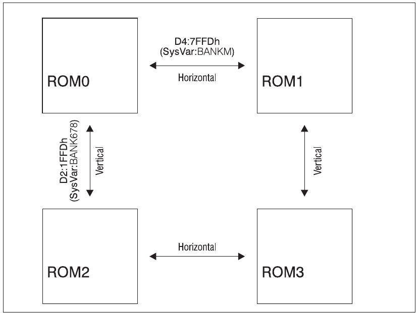
Fig. 49 – Horizontal vs Vertical ROM switching
controls it, is at I/O address 7FFDh (32765). The bit layout for this port is as follows:
| Bit | D7 | D6 | D5 | D4 | D3 | D2 | D1 | D0 |
|---|---|---|---|---|---|---|---|---|
| Description | colour: grey | colour: grey | Disable Paging | ROM Select | Screen Select | RAM Select | ||
D2 to D0 is a three bit number that selects which RAM page goes into the C000h to FFFFh slot. In previous models (such as the +3e) in BASIC, RAM page 0 was normally in-situ, and when editing, RAM page 7 was paged in for various buffers and scratchpads.
D3 switches screens: Screen 0 (the Display + Colour Files) was held in RAM5 (beginning at 4000h) and it was the one that BASIC used, screen 1 was held in RAM7 (beginning at C000h) and could only be used by machine code programs.
D4 determines whether ROM0 (the editor ROM) or ROM1 (the 48K BASIC ROM) is paged into Slot 1 at 0000h to 3FFFh.
D5 is a safety feature – once this bit is set, no further paging operations will work. This is normally used when the machine assumes a standard 48K Spectrum configuration and all the memory paging circuitry is locked out. On previous models, this meant that it couldn't be turned back into a 128K machine other than by rebooting; however, the sound chip can still be driven by OUT either from 48K Basic or machine code. On the ZX Spectrum Next however, you can override that lock switch it back to on by setting NextREG 8, D7 to 1.
Note here that the 16K Bank 5, is the bank read by the ULA to determine what to show on screen for Layer 0 (and 1). The ULA connects directly to the larger memory space ignoring mapping; the screen is always 16K Bank 5, no matter where in memory it is (or if it is switched in at all). Setting D3 of Memory Paging Control (7FFDh) will have the ULA read instead from 16K Bank 7 (otherwise known as "shadow screen"), which can be used as an alternate screen. Beware that this does not map 16K bank 7 into RAM; to alter 16K bank 7 it must be mapped by other means.
Let's now examine the bit layout of port 1FFDh used by the +3.
| Bit | D7 | D6 | D5 | D4 | D3 | D2 | D1 | D0 |
|---|---|---|---|---|---|---|---|---|
| Description | colour: grey | colour: grey | colour: grey | Par. Port Strobe6 | Disk Motor³ | Switch type | ROM / RAM switching | |
When D0 is 0, D1 has no effect and D2 is a "vertical" ROM switch (ie between ROM0 and ROM2 or between ROM1 and ROM3). D4 at 7FFDh on the other hand is a "horizontal" ROM switch (ie. between ROM0 and ROM1, or between ROM2 and ROM3). The following diagram illustrates the various ROM switching possibilities:
It is best to think of D4 in port 7FFDh and D2 in port 1FFDh combining to form a 2-bit number (ranging from 0 to 3) which determines which ROM occupies the memory area 0000h to 3FFFh (16K Slot 1). D4 of port 7FFDh is the least significant bit and D2 of 1FFDh is the most significant bit.
| D2/1FFDh | colour: yellow-green D4/7FFDh | ROM Used |
|---|---|---|
| 0 | 0 | 0 |
| 0 | 1 | 1 |
| 1 | 0 | 2 |
| 1 | 1 | 3 |
ROM switching (with D0 of 1FFDh set to 0)
Tying it all together, we can easily surmise that 128 style memory management can only alter the bank addressed at C000h (For 16K banks that would be Slot 4, or for 8K MMU-type banks Slots 7 and 8). The active 16K bank at C000h is selected by writing the 3 LSBs of the 16K bank number to the bottom 3 bits of Memory Paging Control (7FFDh), and the 4 MSBs to the bottom 4 bits of Next Memory Bank Select (DFFDh). (The reason for the division is that the original Spectrum 128, having only 128k of memory, only needed 3 bits.)
This in essence constructs a "super hardware port" of sorts, very similar to the combination used to select a ROM using bits from 1FFDh and 7FFDh
| D3/DFFDh | D2/DFFDh | D1/DFFDh | D0/DFFDh | colour: yellow-green D2/7FFDh | colour: yellow-green D1/7FFDh | colour: yellow-green D0/7FFDh | Bank |
|---|---|---|---|---|---|---|---|
| 0 | 0 | 0 | 0 | 0 | 0 | 0 | 0 |
| 0 | 0 | 0 | 0 | 0 | 0 | 1 | 1 |
| 0 | 0 | 0 | 0 | 0 | 1 | 0 | 2 |
| … | |||||||
| 1 | 1 | 1 | 1 | 1 | 1 | 1 | 127 |
"Standard Next paging" bank selection settings
If you are using the standard interrupt handler or NextZXOS routines, then any time you write to the Memory Paging Control port (7FFDh) you should also store the value in SysVars at location 5B5Ch. Any time you write to the +3 Memory Paging Control (1FFDh) you should also store the value at 5B67h. There is no corresponding system variable for the Next-only Next Memory Bank Select (DFFDh) port.
6 Not applicable on the ZX Spectrum Next
Note that internally NextZXOS and NextBASIC utilise a combination of all possible banking methods according to what's needed at which time, and you should not rely on this information as a definitive guide on how the system behaves at all times.
allRAM mode
A "Special paging mode" (also called allRAM mode or CP/M mode) is enabled by writing a value with the LSB set to the +3 Memory Paging Control (1FFDh). Depending on the 3 low bits of this value a memory configuration is selected as follows:
| D2/1FFDh | D1/1FFDh | D0/1FFDh | RAM Page combinations (Slot1/.../Slot4) |
|---|---|---|---|
| 0 | 0 | 1 | 0, 1, 2, 3 |
| 0 | 1 | 1 | 4, 5, 6, 7 |
| 1 | 0 | 1 | 4, 5, 6, 3 |
| 1 | 1 | 1 | 4, 7, 6, 3 |
allRAM paging
This mode is selected by default when you select the CP/M Menu from the More… submenu of the Startup menu, or you run the dot command .cpm.
MMU-Based Memory Management
MMU Based memory management is much simpler to use. It only requires a write to the appropriate MMU Next Register to change the 8K bank occupying a specific 8K slot in the 64K address space (See the previous chapter for details on Next Registers). The MMU registers begin with slot 0 in NextREG 80 (50h) and end with slot 7 in NextREG 87 (57h). For MMU0 and MMU1 only, the ROM can be paged in by selecting 255 (FFh) as a bank number. The default values for the MMU Registers are listed in Chapter 23 and correspond to the normal default memory mapping of the 128K Spectrums.
Layer 2 Bank Switching
Layer 2 can also be overlaid on top of the MMU memory map in the bottom 16K or 48K in a Read-only or Write-only mapping. The Write-only mapping, for example, would mean that memory writes to the bottom 16K go to Layer 2 but memory reads come from the MMU mapping as normal. The bottom 16K is normally occupied by the ROM so this Write-only mapping would allow NextBASIC programs to continue to function (the ROM is a read-only program) while allowing POKEs to write into the Layer 2 screen. It is an easy way to gain access to 32K in a single 16K address range.
The Layer 2 mapping is controlled by bits in the Layer 2 Access Port 4667 (123Bh). These bits select among 16K or 48K mapping, Read-only or Write-only, and whether the active Layer 2 screen is mapped or a second Layer 2 buffer (Shadow Screen) is mapped. Layer 2 and its second buffer can be located anywhere in RAM and their starting 16K banks are programmed into NextREG 18 (12h) and 19 (13h) respectively.
The Layer 2 mapping does not have to be used for Layer 2 graphics only; it can be used as a third banking mechanism to access memory more generally.
Paging method interactions
The most recent change to the memory map, whether that is by Standard or MMU methods, always applies. Each time a change is made to the memory map using the Standard mechanism (a write to port 7FFDh, DFFDh, or 1FFDh), the affected MMUs are changed immediately. For example writing to port 7FFDh will change MMU0 and MMU1 to FFh to make sure the selected ROM is visible and MMU6 and MMU7 will be changed to reflect the selected 16K RAM bank.
Paging out the ROM
As seen above, the ROM can be paged out by enabling allRAM mode, or by using MMU based memory management. This may cause problems as some programs may assume
that ROM-based service routines are present at fixed addresses in ROM. Additionally, if the default interrupt mode (IM1) is set, the CPU will JP to 0038h every frame trying to find an interrupt handler routine. If it does not, (which it won't unless you write your own), the system will crash.
ZX Spectrum Next User Manual, 3rd Edition (ISBN 978-1-5272-5496-1), written and illustrated by Phoebus R. Dokos. Copyright © 2020-2024 Phoebus Dokos / SpecNext Ltd. Licensed under CC BY-NC-SA 4.0. This is a transcription and can contain errors; check any doubt against the printed page.